Prosthetic implant and method

a technology of prosthesis and implant, applied in the field of prosthesis or implant, can solve the problems of increasing the stress on adjacent spinal motion segments, lack of mobility,

Active Publication Date: 2006-05-04
X SPINE SYST
View PDF37 Cites 82 Cited by
  • Summary
  • Abstract
  • Description
  • Claims
  • Application Information

AI Technical Summary

Benefits of technology

[0010] In still another aspect, this invention comprises an implant comprising: a first member for mounting onto a first vertebra, the first member comprising a first channel; a second member for mounting onto a second vertebra, the second member comprising a second channel; and a ball situated in the first and second channels when the first and second members are mounted to the first and second vertebrae, respectively; the first and second channels each comprising a channel width and channel length; the ball having a circumference that is smaller than both the channel width and the channel length, the channel width being less than the channel length.

Problems solved by technology

Unfortunately, spinal fusion has several drawbacks, including preventing the fused vertebrae from moving rotationally or translationally with respect to each other, as natural disc tissue permits.
The lack of mobility may increase the stresses on adjacent spinal motion segments.

Method used


Image

  • Prosthetic implant and method
  • Prosthetic implant and method
  • Prosthetic implant and method

Examples


Embodiment Construction

[0029] In the following detailed description, for purposes of explanation and not with limitation, examples and embodiments showing specific details are set forth in order to provide a thorough understanding of the present invention. However, it will be apparent to one having ordinary skill in the art having had the benefit of the present disclosure, that the present invention may be practiced in other embodiments that depart from specific details disclosed herein. Moreover, description of well-known apparati and methods may be omitted so as not to obscure the description of the present invention. Such methods and apparati are clearly within the contemplation of the inventor in carrying out the example embodiments. Wherever possible, like numerals refer to like features throughout.

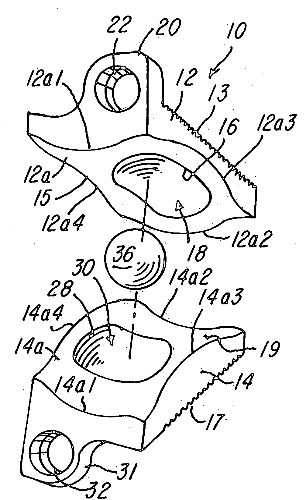
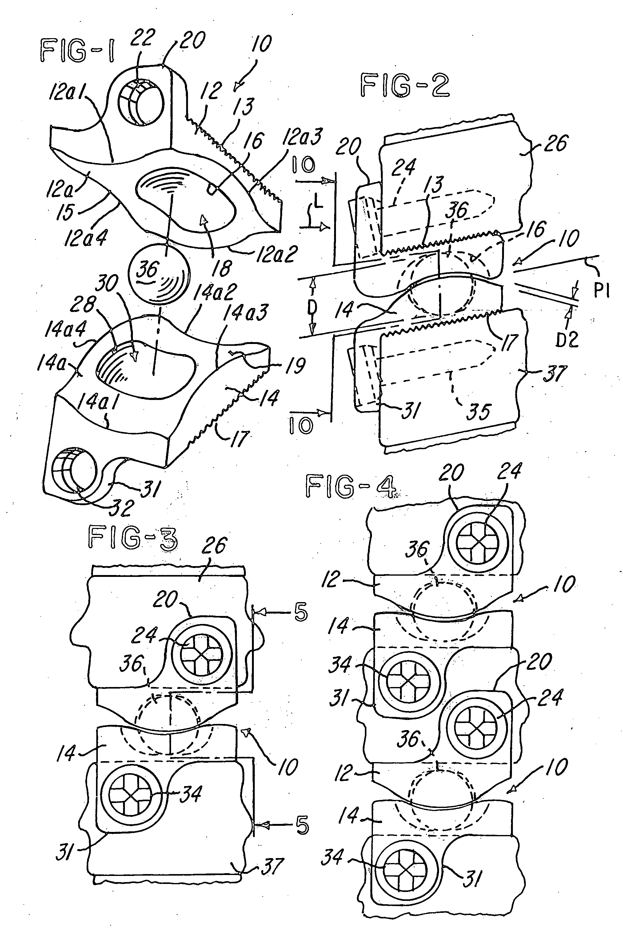
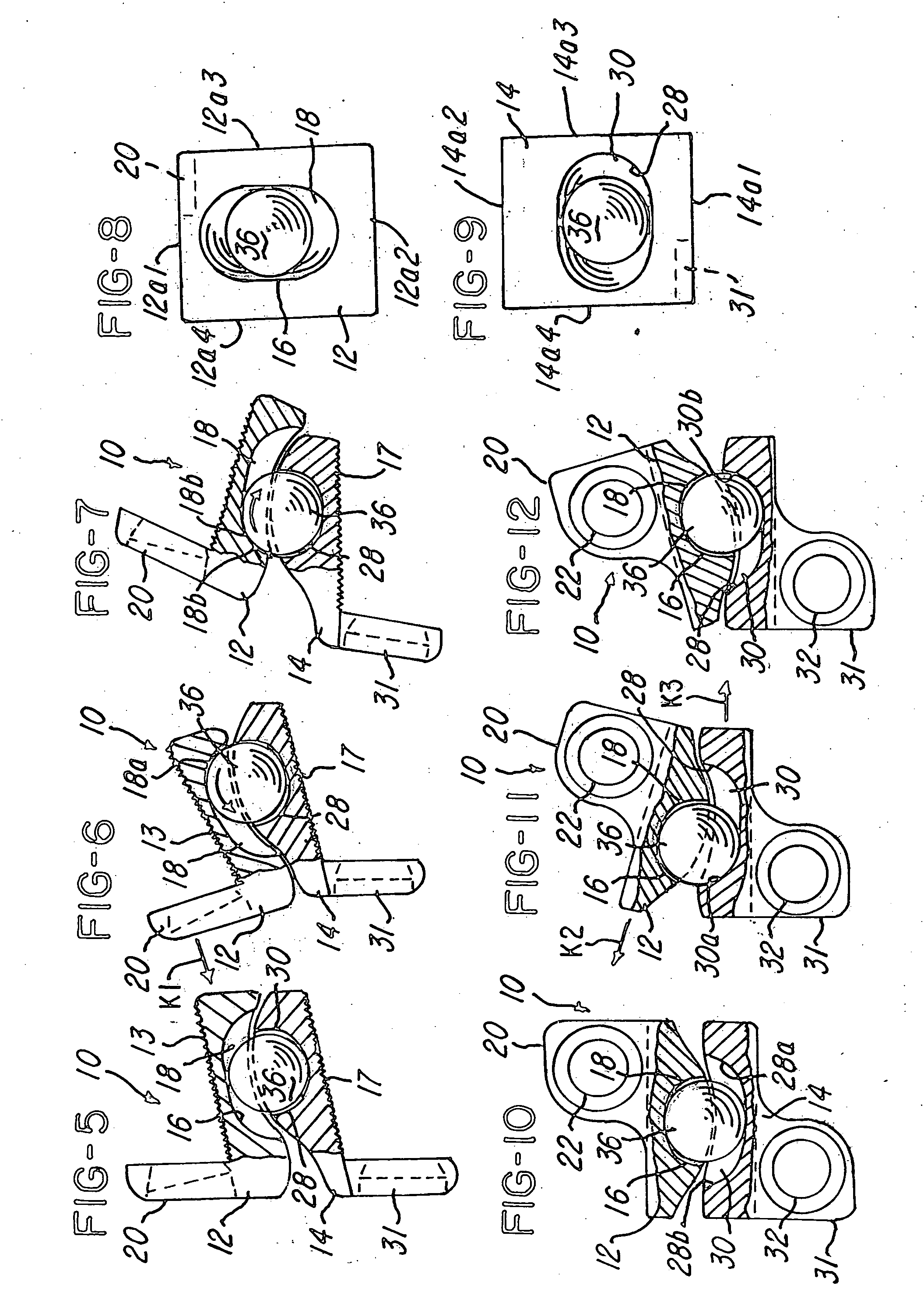
[0030] Referring now to FIG. 1, a prosthesis, implant or prosthetic implant 10 is shown. The implant 10 comprises an upper, top, superior or first member 12 and a lower, bottom, inferior or second member ...


PUM


Abstract

An implant having a first member having a first elongated channel and a second member having a second elongated concave channel that becomes generally opposed when the first and second members are mounted to a first and second vertebra. A ball bearing is received in each of the channels to both separate and maintain a predetermined distance between the first and second member and also to facilitate movement in a plane that intersects an axis of the spinal column. The ball bearing is seated in and cooperates with the channels to permit pivotal movement about a plurality of axes. A method for replacing a disc is also shown using the implant.

Description

BACKGROUND OF THE INVENTION [0001] The present invention is directed to a prosthesis or implant for use as an intervertebral disc prosthesis having a first member having a first area, groove or channel, a second member having a second area, groove or channel, and a ball bearing for situating in said first and second area, groove or channels. [0002] In cases where intervertebral disc tissue is removed or is otherwise absent from a spinal segment, corrective measures are indicated to insure proper spacing of the vertebrae formally separated by the removed disc tissue. Commonly, the two vertebrae may be fused together using transplanted bone tissue, and artificial fusion element, or other compositions or devices. Unfortunately, spinal fusion has several drawbacks, including preventing the fused vertebrae from moving rotationally or translationally with respect to each other, as natural disc tissue permits. The lack of mobility may increase the stresses on adjacent spinal motion segment...

Claims


Application Information

Patent Timeline
Patent Type & Authority Applications(United States)
IPC IPC(8): A61F2/44
CPCA61F2/4425A61F2002/30242A61F2002/30578A61F2002/30642A61F2002/30663A61F2002/30904A61F2002/443A61F2002/449A61F2230/0071A61F2310/00017A61F2310/00023A61F2310/00029A61F2310/00203A61F2310/00239
Inventor KIRSCHMAN, DAVID LOUIS
Owner X SPINE SYST
Why Eureka
Try Eureka