
Computer controlled cup forming machine

a cup forming machine and computer control technology, applied in the field of drinking cup forming machines, can solve the problems of nevertheless having certain limitations

Active Publication Date: 2006-05-04
SOLO CUP OPERATING CORP
View PDF99 Cites 52 Cited by
  • Summary
  • Abstract
  • Description
  • Claims
  • Application Information

AI Technical Summary

Benefits of technology

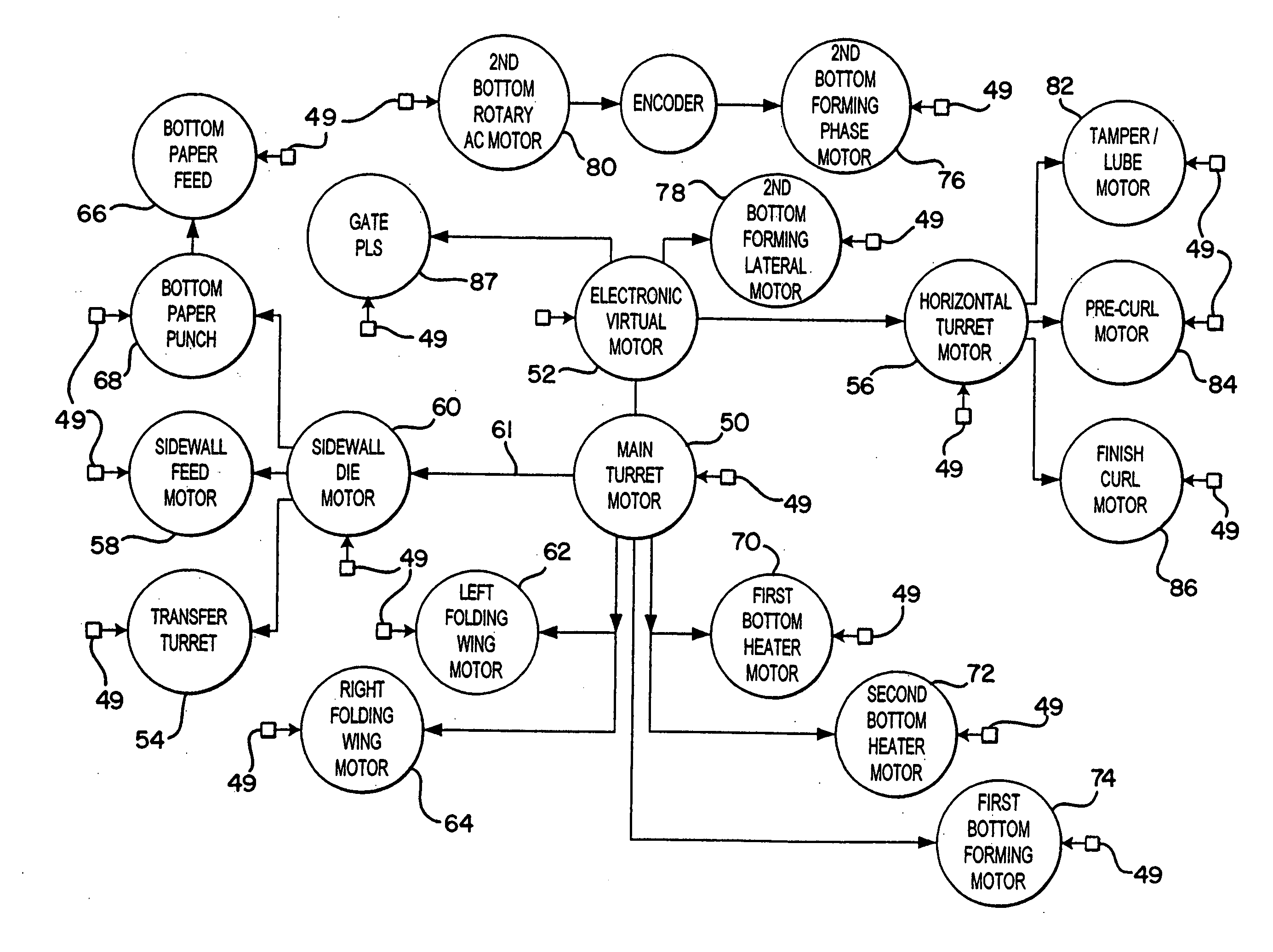
[0008] According to another embodiment, an input station is electrically connected to the main controller. At the input station an operator can quantitatively adjust control parameters for the motors. The main controller sends signals to the motors of the adjusted control parameters to assist in quantitatively controlling the motion of the motors. In one embodiment a dwell period for the drive profiles for the motors can be adjusted at the input station and set independent of the machine speed of the cup forming machine.

Problems solved by technology

While such cup forming machines according to the prior art provide a number of advantageous features, they nevertheless have certain limitations.

Method used


Image

  • Computer controlled cup forming machine
  • Computer controlled cup forming machine
  • Computer controlled cup forming machine

Examples


Embodiment Construction

[0046] While this invention is susceptible of embodiments in many different forms, there is shown in the drawings and will herein be described in detail preferred embodiments of the invention with the understanding that the present disclosure is to be considered as an exemplification of the principles of the invention and is not intended to limit the broad aspect of the invention to the embodiments illustrated.

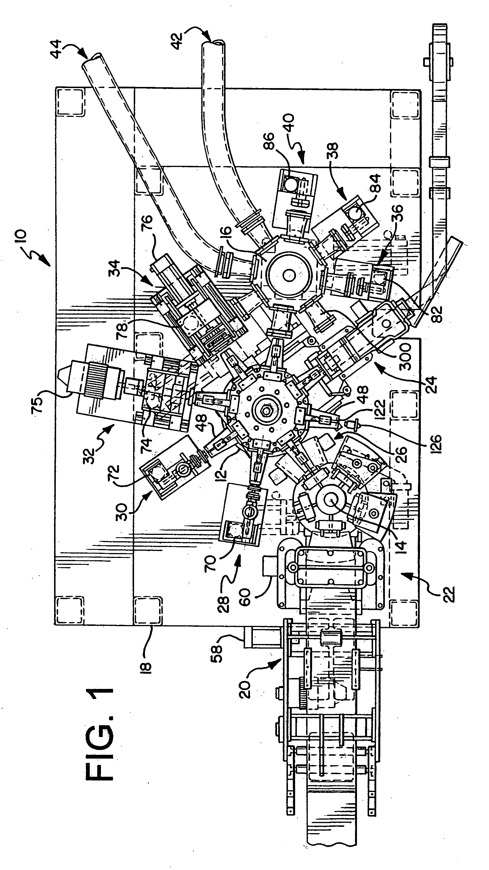
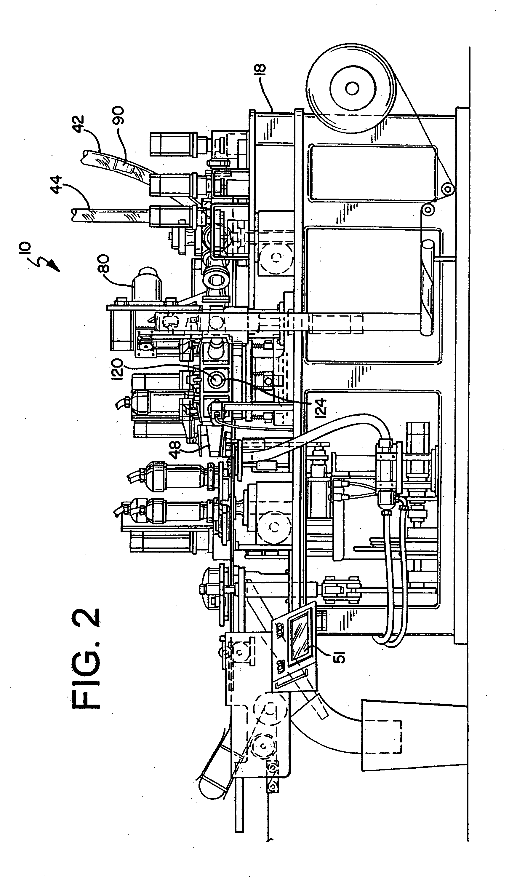
[0047] Referring now to the Figures, and specifically to FIGS. 1 and 2, there is shown a cup forming machine 10. The cup forming machine 10 in the present example generally comprises a main or mandrel turret 12, a transfer turret 14, and a rimming turret 16 mounted on a frame 18, however, the cup forming machine may be comprised of a variety of turrets and workstations in a variety of configurations. In the exemplar embodiment, each of the turrets 14, 16, 18 are horizontal-type turrets.

[0048] Turning again to FIGS. 1 and 2, a plurality of workstations surround the mandrel tu...


PUM


Abstract

A computer controlled cup forming machine is provided. The computer controlled cup forming machine has a main motor, a main controller, and a plurality of workstations having individual motors electrically connected to the main motor and the main controller. The main controller develops electrical signals of a drive or motion profile that are sent to the individual motors, and the main motor sends additional electrical signals to the individual motors to initiate the drive profiles at the individual motors. The main controller also has an input station to quantitatively control each of the individual motors.

Description

CROSS-REFERENCE TO RELATED APPLICATIONS [0001] Not Applicable. FEDERALLY SPONSORED RESEARCH OR DEVELOPMENT [0002] Not Applicable. TECHNICAL FIELD [0003] The present invention relates generally to a machine for forming drinking cups, and more specifically to a computer controlled multi-axis paper cup forming machine. BACKGROUND OF THE INVENTION [0004] Cup forming machines are well known in the art. Such machines are generally used to convert a substrate into a formed cup having a sidewall and a bottom. While such cup forming machines according to the prior art provide a number of advantageous features, they nevertheless have certain limitations. The present invention seeks to overcome certain of these limitations and other drawbacks of the prior art, and to provide new features not heretofore available. A full discussion of the features and advantages of the present invention is deferred to the following detailed description, which proceeds with reference to the accompanying drawings...

Claims


Application Information

Patent Timeline
Patent Type & Authority Applications(United States)
IPC IPC(8): G06F19/00
CPCB31B1/32B31B17/00B31B2201/2612B31B2201/95B31B2217/082B31F5/00G05B2219/42186B31B50/32B31B50/006B31B2105/0022
Inventor MANNLEIN, DEAN JOSEPHPYPER, THOMAS DAVID JR.
Owner SOLO CUP OPERATING CORP
Learn More