Interface unit for automation systems and method of providing and installing such an interface

a technology of automation system and interface unit, applied in the field of automation system, can solve the problems of many vendors and manufacturers of these machines that cannot provide individual interfaces, and new standards provide additional functionality which often cannot be used

Inactive Publication Date: 2006-05-04
SIEMENS AG
View PDF4 Cites 21 Cited by
  • Summary
  • Abstract
  • Description
  • Claims
  • Application Information

AI Technical Summary

Benefits of technology

[0015] The unit may further comprise at least a third interface coupled with the data acquisition unit for coupling additional hardware with the unit. The additional hardware can be a barcode reader used with the machine or installation. The additional hardware can also be a sensor used with the machine or installation. The sensor can be selected from the group consisting of temperature sensor, humidity sensor, and pressure sensor. The third interface can be a graphical user interface used for controlling the machine or installation. The additional hardware can be an external control circuit used with the machine or installation. The data acquisition unit may comprise a microprocessor or microcontroller. The unit can be integrated within a fan-less housing. The plurality of data interfaces can be selected from the group consisting of SECS/GEM interface, EDA interface, EPT interface, and e-diagnostic interface. The plurality of data interfaces may include at least one 300 mm semiconductor standard interface. The data acquisition unit may further comprise a cell controller for controlling machine specific functions of an automation process. The first interface may include an Ethernet, a field bus and/or a serial interface.
[0016] Another exemplary communication interface unit for integrating a semiconductor

Problems solved by technology

However, many vendors and manufacturers of these machines either cannot provide for individual interfaces because individual functionality and interface specifications of a specific engineering s

Method used


Image

  • Interface unit for automation systems and method of providing and installing such an interface
  • Interface unit for automation systems and method of providing and installing such an interface
  • Interface unit for automation systems and method of providing and installing such an interface

Examples


Embodiment Construction

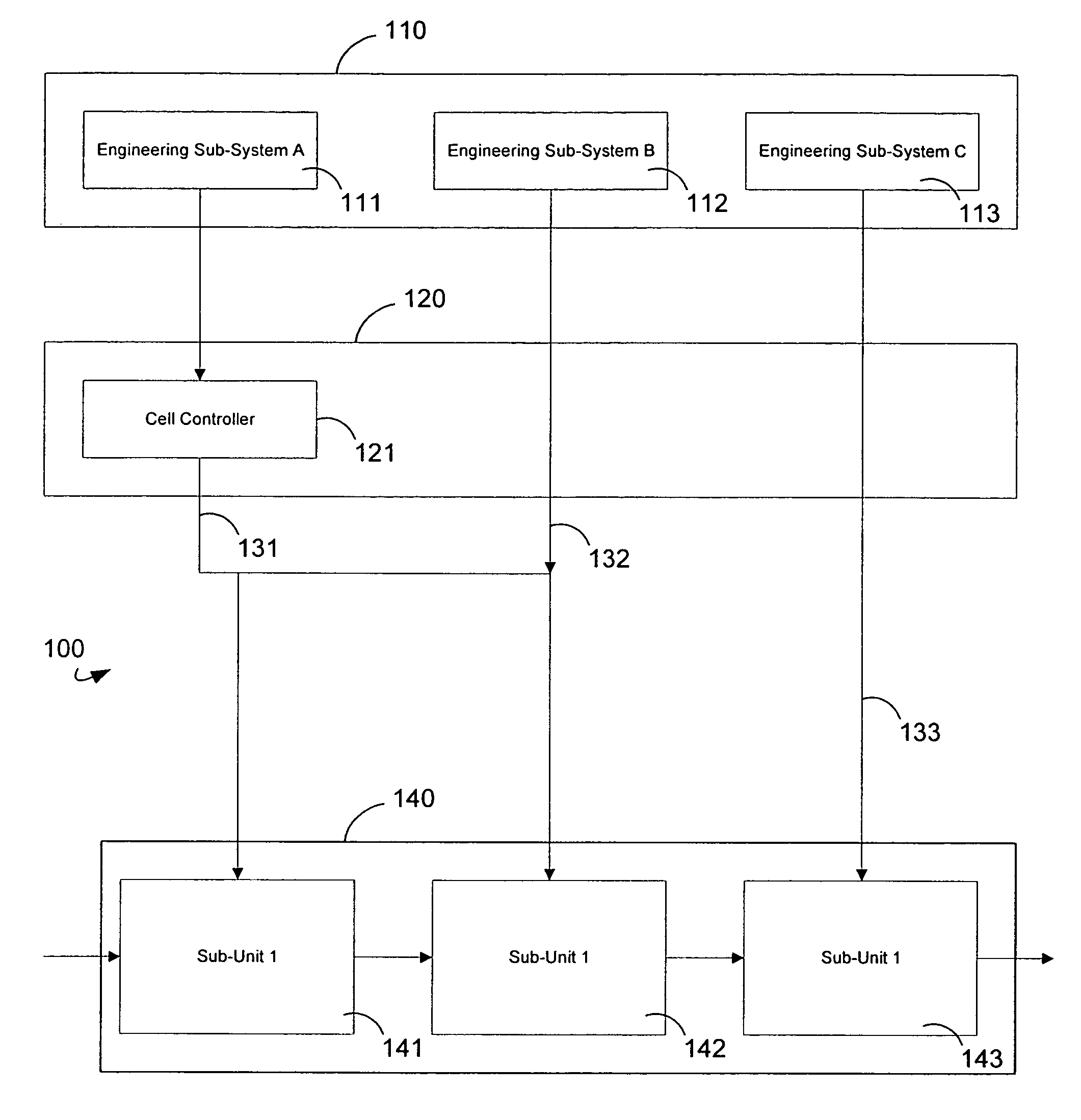
[0022]FIG. 1 shows a conventional automation system 100 including an engineering system 110 with engineering sub-systems A, B, and C designated with numerals 111, 112, and 113, respectively. An integration layer 120 is also provided which includes for example a cell controller 121 which is coupled, for example, with one of the engineering systems, in this exemplary embodiment with engineering system A. A cell controller provides for adaptation software for a specific machine and or installation and, thus, provides for individual custom control functions of a machine or installation. A machine or installation 140 may include a plurality of sub-systems 141, 142, and 143 which may form a manufacturing machine such as, for example, an etcher. Different individual customary couplings 131, 132, and 133 connect the engineering systems 111, 112, and 113 with one or more sub-systems 141, 142, and 143 of the machine or installation 140. In this exemplary embodiment, sub units 141 and 142 rece...


PUM


Abstract

A method of integrating a machine or installation into an engineering/control system within the facility, such as an automation system, comprises the steps of receiving a definition or specification for applicable standards for communication between the engineering/control system within the facility and the machines or installations; manufacturing or providing a communication interface unit comprising enhanced interfaces to fulfill the definition or specification and adapting the communication interface unit to the definition or specification; providing the communication interface unit to a machine or installation manufacturer for manufacturing the machine or installation; delivering the machine or installation and the communication interface unit to the facility; and integrating the machine or installation equipped with the communication interface unit within the facility.

Description

TECHNICAL FIELD OF THE INVENTION [0001] The present application relates to automation systems and in particular to the integration of production and or manufacturing machines within a factory or plant. BACKGROUND OF THE INVENTION [0002] In modern factories or plants, engineering systems are provided to define processing steps in manufacturing and / or controlling certain process steps within the system. To this end, these engineering systems usually have to be coupled with the respective machines or installations to mirror the internal operating sequences within the engineering system. To this end the manufacturer or vendor of a respective machine or installation needed to provide the machine or installation with a data interface that was capable of complying with the existing standards of the engineering system to be controlled by them. However, many vendors and manufacturers of these machines either cannot provide for individual interfaces because individual functionality and interf...

Claims


Application Information

Patent Timeline
IPC IPC(8): G06F15/177
CPCG05B2219/32033H04L67/34H04L67/125
Inventor DREYER, THOMASLIMMER, GERD
Owner SIEMENS AG
Why Eureka
Try Eureka