Method and apparatus for the lamination of band-shaped uncured rubber materials

Inactive Publication Date: 2006-05-11
BRIDGESTONE CORP
View PDF11 Cites 32 Cited by
  • Summary
  • Abstract
  • Description
  • Claims
  • Application Information

AI Technical Summary

Benefits of technology

[0013] It is, therefore, an object of the invention to solve the afore-mentioned problems in the manufacture of the tire and other rubber composite and to provide a method for laminating band-shaped uncured rubber materials in a high productivity capable of establishing the sufficient holdin

Problems solved by technology

Therefore, it is obliged to more complicate the molding step.
As a result, the complete automation of the molding step is difficult and it is still the present state to require a hand work.
However, as the hand work is added, a big improvement of molding efficiency can not be attained and the accuracy of laying various materials lowers.
As a result of satisfying such a demand, there is caused a difference in the property between adjoining rubbers such as a considerably large modulus difference or the like.
Therefore, when the tire is run under loading over a long distance of several ten thousands kilometers, strain repeatedly and concentrically acts to these joint faces over a long time.
As a result, troubles such as separation and the like are easily caused in the joint faces to lower the durability.
However, the above publication does not mention such troubles and the countermeasure for holding or improving the durability at all.
On the other hand, in the rubber composites inclus

Method used


Image

  • Method and apparatus for the lamination of band-shaped uncured rubber materials
  • Method and apparatus for the lamination of band-shaped uncured rubber materials
  • Method and apparatus for the lamination of band-shaped uncured rubber materials

Examples


Embodiment Construction

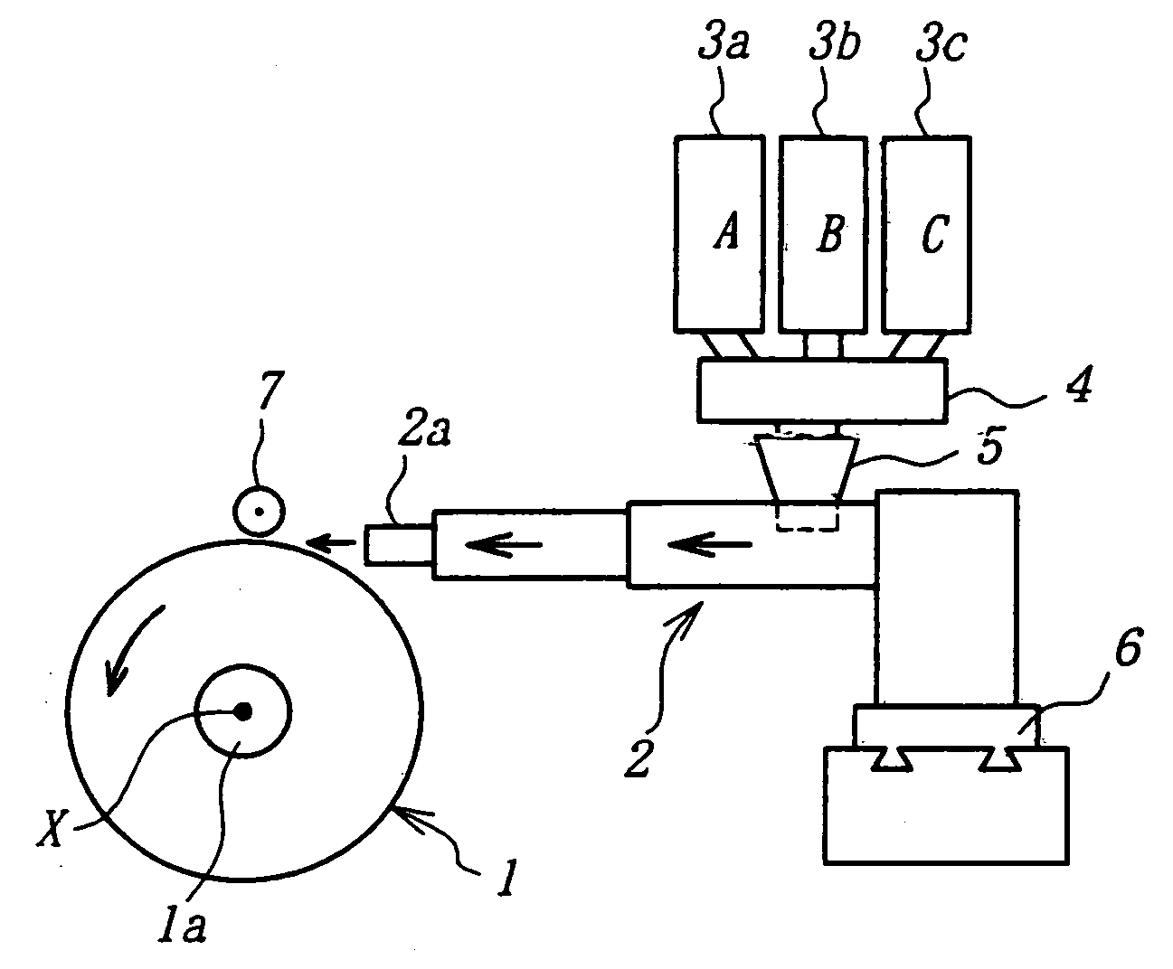
[0042] As shown in FIG. 1, the apparatus for laminating band-shaped uncured rubber materials according to the invention comprises a combination of a support 1 and an extruder 2.

[0043] The support 1 is attached to a shaft la rotating by a driving source (not shown). The support means a forming drum, a intermediate body formed by winding a part of uncured rubber material, uncured rubberized cords and the like on the forming drum, a base tire for retreading and so on. Moreover, the base tire is a tire obtained by removing a remaining tread rubber or the like from a used tire.

[0044] A band-shaped uncured rubber material is wound on a surface of the support. In this case, an extruder 2 is arranged so as to locate a band-shaped rubber material feeding portion 2a of the extruder 2 in the vicinity of the surface of the support 1. The feeding portion 2a is provided with a usual extrusion die or a pair of upper and lower roll dies instead of the extrusion die.

[0045] The extruder 2 is provi...


PUM

PropertyMeasurementUnit
Fractionaaaaaaaaaa
Fractionaaaaaaaaaa
Pressureaaaaaaaaaa

Abstract

In the lamination of band-shaped uncured rubber materials to form a laminated rubber member having a given sectional shape by helically winding a band-shaped uncured rubber material extruded through an extruder on a rotating support, two or more rubber compositions indicating different moduli after the curing are used as a rubber material fed to the extruder, and a first rubber material is extruded through the extruder and helically wound on the support to form a first rubber layer, and the first rubber material and a second rubber material are continuously and simultaneously through the extruder so as to stepwise or gradually increase a blending ratio of the second rubber material to the first rubber material while holding the same extrusion sectional shape and helically wound on the first rubber layer while overlapping with at least a part of the first rubber layer to form a second rubber layer.

Description

[0001] This is a Division of application Ser. No. 09 / 347,525 filed Jul. 6, 1999. The entire disclosure of the prior application is hereby incorporated by reference herein in its entirety. BACKGROUND OF THE INVENTION [0002] 1. Field of the Invention [0003] This invention relates to a method and an apparatus for the lamination of band-shaped uncured rubber materials, and more particularly to a method of extruding two or more uncured rubber materials having different moduli (modulus of elasticity) after the curing through an extruder and laminating the extruded band-shaped rubber materials on a rotating support to form a set of rubber members and an apparatus for realizing such a method. Particularly, the invention relates to a method and an apparatus for the lamination of band-shaped uncured rubber members in the building of a pneumatic tire. [0004] 2. Description of Related Art [0005] In the production of the composite comprised of various rubbers, a step of laying various uncured ru...

Claims


Application Information

Patent Timeline
IPC IPC(8): B29D30/08B60C5/14B29C48/07B29C48/18B29C53/58B29D30/60B29D30/62
CPCB29C47/0019B29C47/06B29C53/581B29D30/60B29K2021/00B29K2105/246B29C47/1045B29C47/1081B60C1/0008B29C48/297B29C48/07B29C48/18B29C48/2886
Inventor OKU, MASAHARUOGAWA, YUICHIROHATAKEYAMA, KAZUYA
Owner BRIDGESTONE CORP
Why Eureka
Try Eureka