Propulsion and attitude control systems for aircraft

Inactive Publication Date: 2006-05-11
RIVERS
View PDF9 Cites 9 Cited by
  • Summary
  • Abstract
  • Description
  • Claims
  • Application Information

AI Technical Summary

Problems solved by technology

Although this approach is advantageous because it reduces power required and consequent fuel flow rate in vertical flight as well as the effects of hot engine efflux and blast on the ground, the major performance disadvantage with helicopters generally is that at some horizontal speed, sometimes referred to as the physical maximum horizontal limiting speed, either the retreating blades no longer create sufficient lift, the advancing blades reach supersonic speeds, or both.
In addition and in any event, the rotor disk physically creates drag in forward flight mode and thereby impairs the performance envelope in forward flight.
Thus, helicopt

Method used


Image

  • Propulsion and attitude control systems for aircraft
  • Propulsion and attitude control systems for aircraft
  • Propulsion and attitude control systems for aircraft

Examples


Embodiment Construction

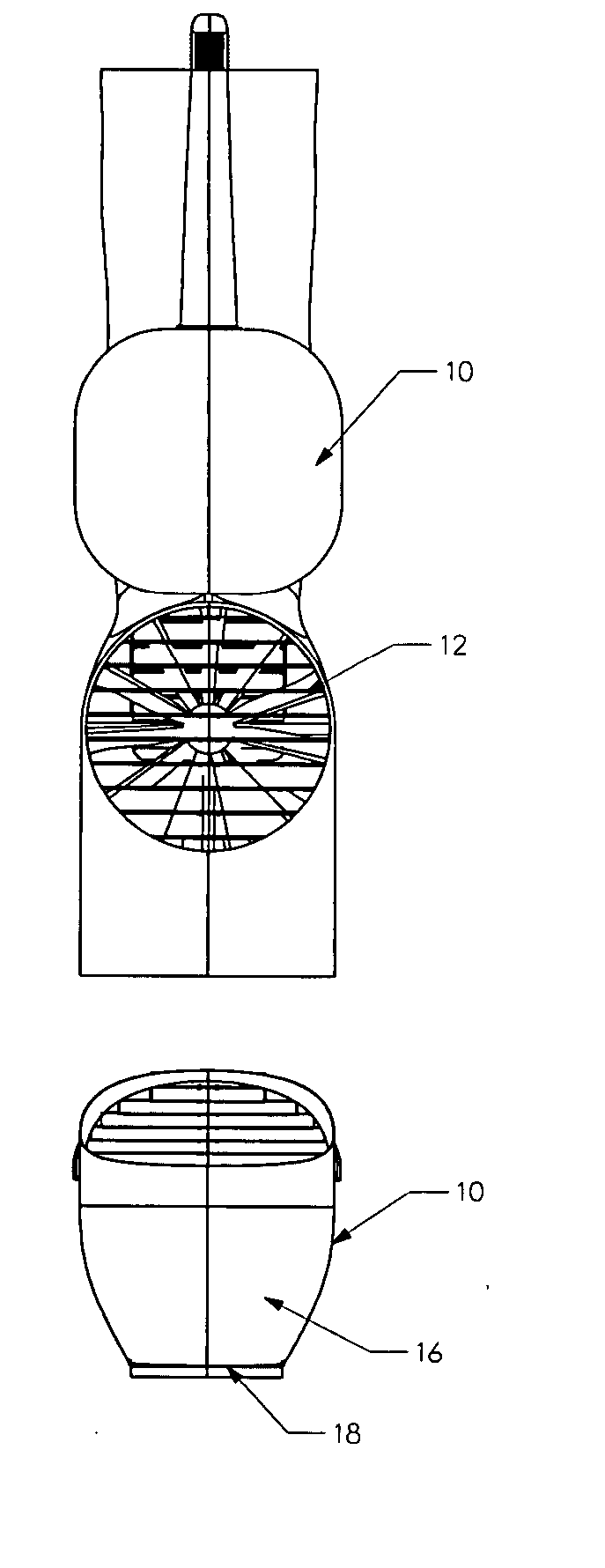
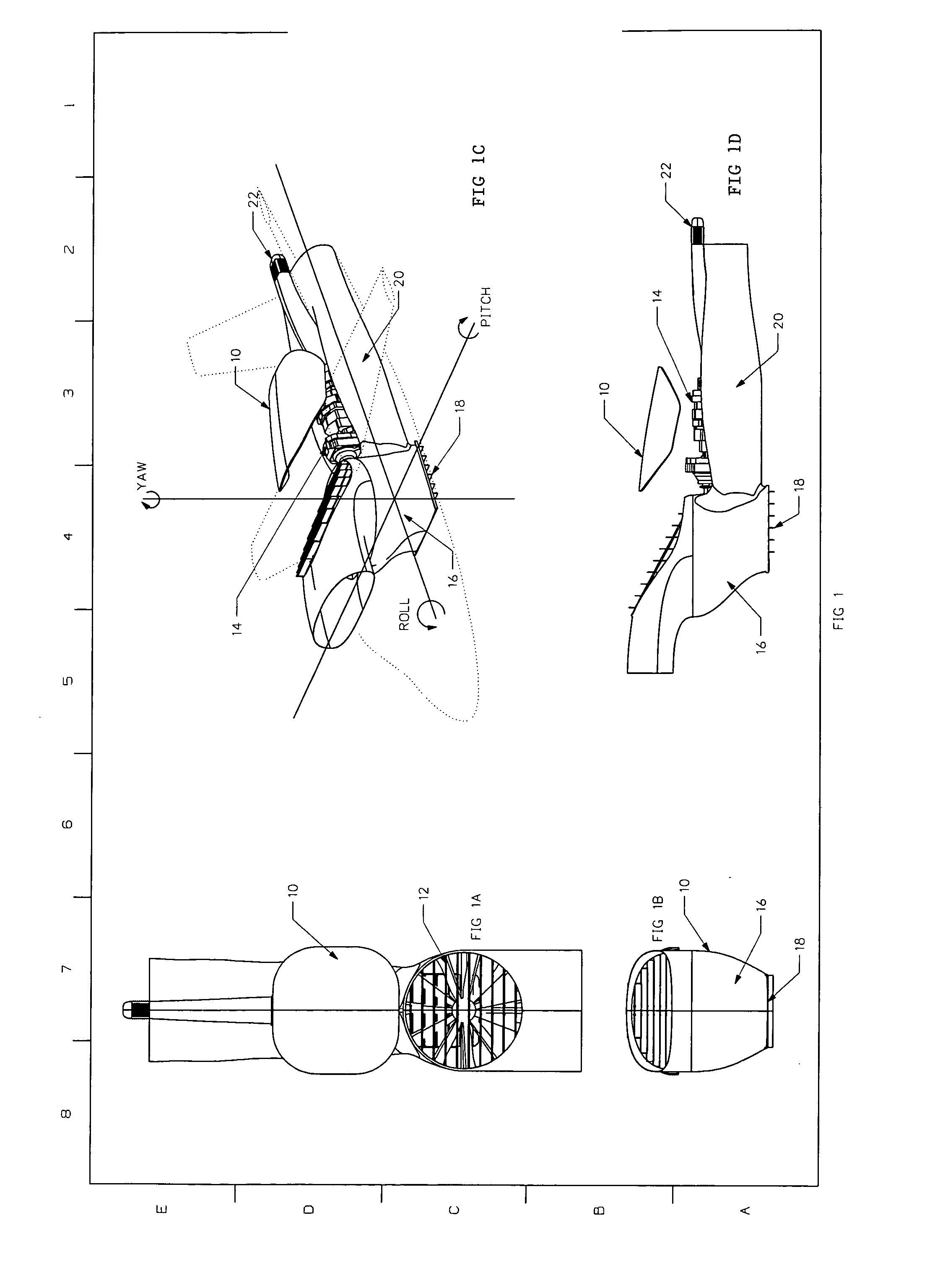
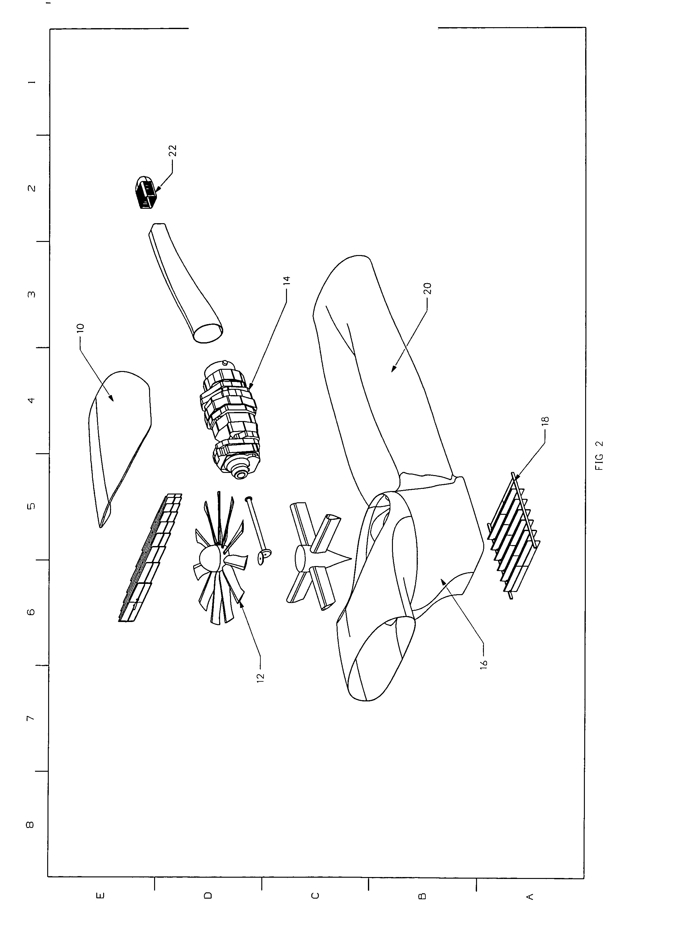
[0035] FIGS. 1 A-D show a preferred embodiment of systems according to one aspect of the invention for propelling and controlling attitude of an aircraft. As shown in these figures, system 10 comprises a fan 12 which is coupled to a propulsion unit 14. The fan is preferably oriented so that it rotates about an axis substantially parallel to the yaw axis of the aircraft. The fan is also preferably but not necessarily located so that its rotational axis contains or is near, or generally aligned with, the aerodynamic center or center of gravity of the aircraft throughout a desirable part of at least the vertical flight envelope. Fan 12 may contain fixed pitch or controllably variable pitch vanes or blades as desired. Fan 12 is preferably coupled to a propulsion unit 14 which may be a high specific energy turbo shaft engine which can be mounted, but need not be, so that its output shaft or turbine shaft is oriented generally parallel to the roll axis of the aircraft. In this manner, thr...


PUM


Abstract

Systems for propelling and controlling attitude of aircraft. Systems according to certain embodiments of the invention employ a fan whose rotational axis is preferably generally parallel to the yaw axis of the aircraft and which is preferably generally aligned with the center of gravity of the aircraft at least during the vertical phases of flight. Efflux from the fan can be routed downward through a vertical outlet for providing lift and vertical flight, and aft through a propulsion duct for providing thrust in horizontal flight modes. Vanes in the vertical outlet can be used to direct flow of efflux more in a forward or aft direction for “balancing” of the aircraft about the rotor in vertical flight. A vector unit located away from the center of gravity of the aircraft, such as in or near the tail of the aircraft, through which engine efflux can be routed, employs vanes to direct efflux flow, in a controllable fashion, upward, downward, port and/or starboard for commensurate control of the pitch and yaw of the aircraft.

Description

[0001] This invention relates to systems and processes for propelling and controlling the attitude or orientation of an aircraft about its yaw, pitch and / or roll axis in vertical and horizontal flight. BACKGROUND [0002] Since the dawn of aviation, designers have desired to create aircraft which featured not only a horizontal flight performance envelope that allowed superior performance, such as climb, endurance, range and speed, but also the ability to take off and land vertically in a minimum of space. [0003] One of the first approaches involved Igor Sikorski and others who developed multiple and single rotor helicopter systems. Helicopters with their lengthy, typically variable pitch rotors, offer superior disk loading, that is they accelerate a large disc of air downwardly an incremental amount to lift the aircraft. Although this approach is advantageous because it reduces power required and consequent fuel flow rate in vertical flight as well as the effects of hot engine efflux ...

Claims


Application Information

Patent Timeline
IPC IPC(8): B64C29/00
CPCB64C27/20
Inventor STONE, C. RIVERSRICHARDSON, CHADWITTENBORN, GRANTANEMAAT, WILLIAM A.
Owner RIVERS
Why Eureka
Try Eureka