Switched reluctance machine

Active Publication Date: 2006-05-11
TURNTIDE TECH INC
View PDF23 Cites 10 Cited by
  • Summary
  • Abstract
  • Description
  • Claims
  • Application Information

AI Technical Summary

Benefits of technology

[0007] The present invention provides a switched reluctance machine (SRM); whether operated as a motor, generator, or both; having a new relationship between the number of stator poles and rotor poles so as to provide a SRM with a minimal amount of torque ripple and acoustic noise while providing improved power density and torque production. Particularly, the present invention provides a SRM having a salient rotor and stator pole numerical relationship of S number of stator poles, where S>4, and R number of rotor poles, which can be expressed as R=2S−2, such as a S / R pole count in a 6 / 10, 8 / 14, or 10 / 18 configuration.

Problems solved by technology

This results in considerable torque ripple and is one of the factors limiting the application of SRMs.

Method used


Image

  • Switched reluctance machine
  • Switched reluctance machine
  • Switched reluctance machine

Examples


Embodiment Construction

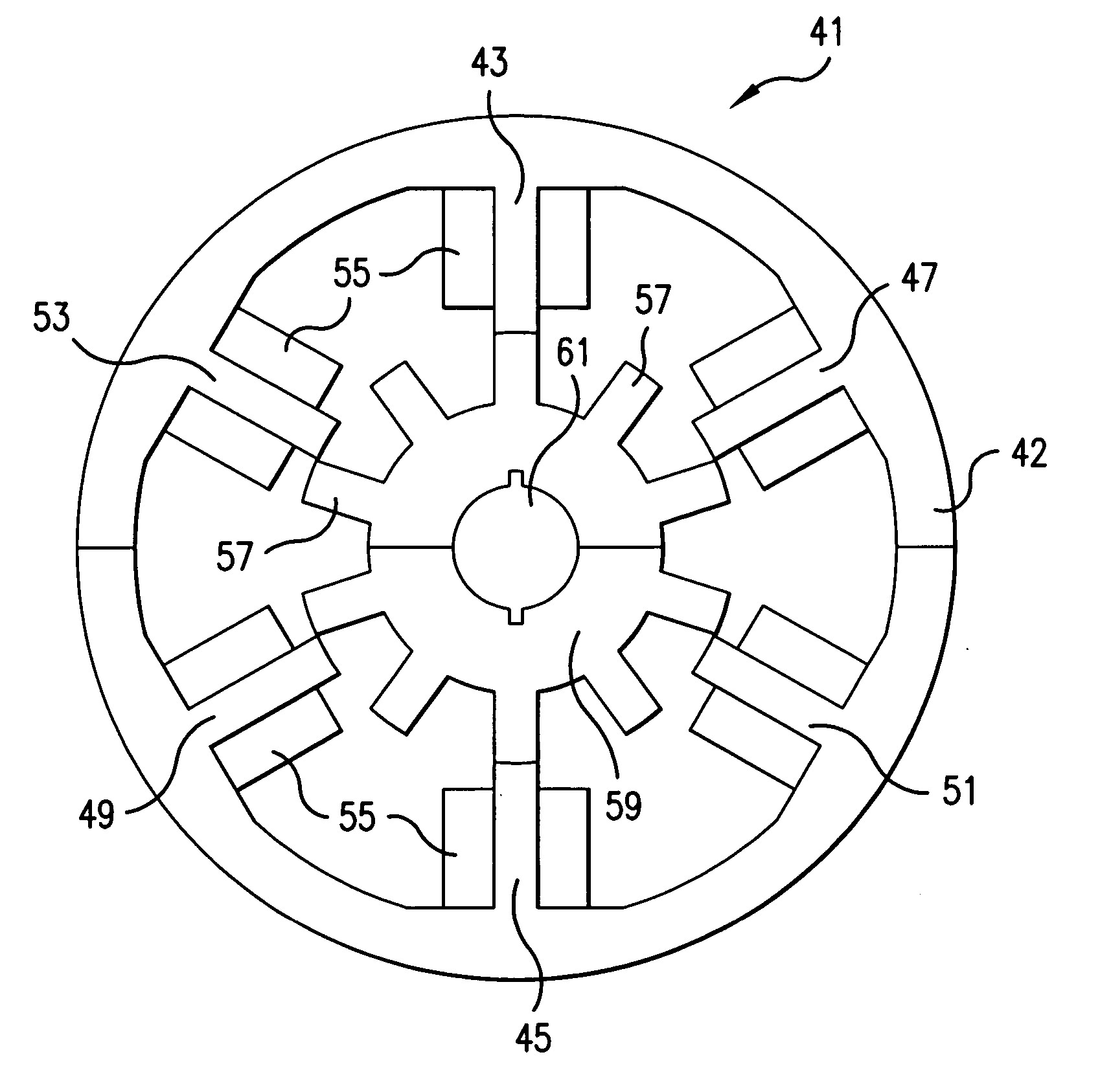
[0022] The exemplary embodiment will be set forth in the context of a rotary switched reluctance machine (SRM). It will be appreciated by the person having ordinary skill in the art that a SRM according to the present invention may be arranged in a variety of ways.

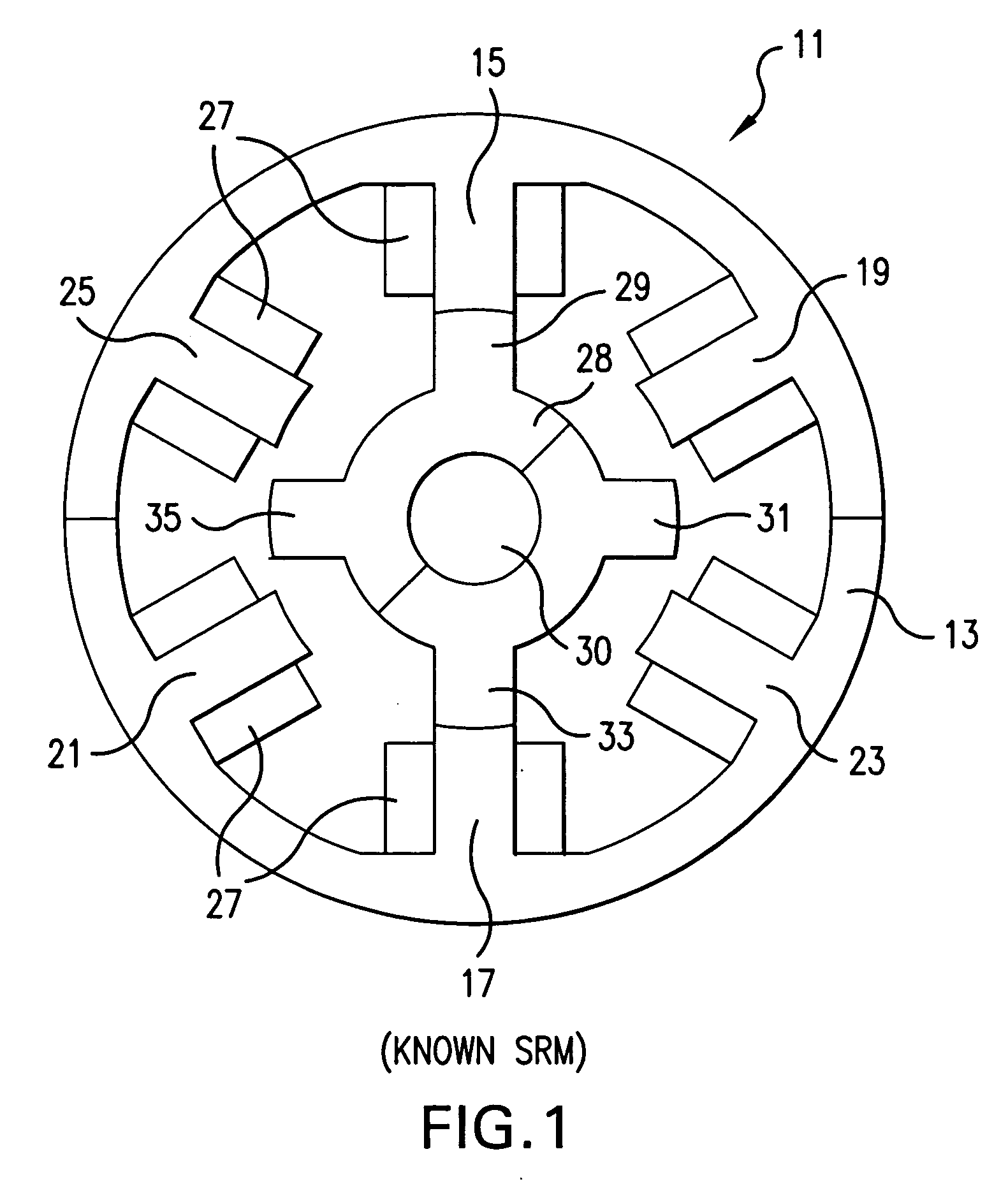
[0023]FIG. 1 illustrates a known construction of a three-phase salient pole SRM 11. The outer stator 13 has six poles 15, 17, 19, 21, 23, 25 each having a coil, collectively 27, wound around each stator pole. The coils on diametrically opposite stator pole pairs i.e. 15 / 17, 19 / 21, and 23 / 25 are connected in series or in parallel to form a phase of the machine. In general, the number of poles in a stator is double the number of phases. Hence, the machine shown in FIG. 1 is a three-phase machine (Phases A, B and C) with six stator poles 15 / 17, 19 / 21, and 23 / 25, respectively. The rotor 28, affixed to central rotatable shaft 30, has four rotor poles 29, 31, 33, 35.

[0024] To operate the SRM 11 as a motor, each phase is normal...


PUM


Abstract

A switched reluctance machine (SRM) having a rotor and stator pole numerical relationship of S number of stator poles and R number of rotor poles, where R=2S−2, when S is greater than 4; provides improved power density, torque production, torque ripple, and acoustic noise, and is readily adaptable to existing hardware such as known controllers and the like.

Description

BACKGROUND OF THE INVENTION [0001] 1. Field of the Invention [0002] The present invention relates generally to a switched reluctance machine (SRM). The present invention relates more specifically to a SRM having a new relationship between the number of stator poles and rotor poles. [0003] 2. Discussion of the Related Art [0004] A switched reluctance machine has salient poles on its stationary member stator and rotating member rotor. SRMs are advantageous in their operation because they do not require permanent magnets or field windings on the rotor. Because of simple and robust construction, fault tolerant capabilities and torque-speed characteristics, SRMs are very popular to provide auxiliary power in aircraft, automotive and vehicular systems, non-conventional energy sources, and other industrial machineries and equipments. [0005] SRMs are realized in a variety of forms. In particular, the constructions differ in the number of stator and rotor poles on the stationary and movable ...

Claims


Application Information

Patent Timeline
IPC IPC(8): H02K17/00H02K17/42H02K19/20
CPCH02K1/246H02K19/103
Inventor DESAI, PIYUSH C.EMADI, ALI
Owner TURNTIDE TECH INC
Why Eureka
Try Eureka