Origin adjusting device of industrial robot

Inactive Publication Date: 2006-05-11
PANASONIC CORP
View PDF5 Cites 0 Cited by
  • Summary
  • Abstract
  • Description
  • Claims
  • Application Information

AI Technical Summary

Benefits of technology

[0011] By this construction, an origin adjustment can be realized which is inexpensive and highly accurate and which requires extremely few man hours. Furthermore, since the invention requires no special signal line for origin adjustment due to the construction in which no signal generating device such as a switch is provided, despite the fact that the positioning m

Problems solved by technology

In addition, as a result of this, the construction becomes complex and the joint member of the robot as well as the origin adjustment apparatus become expensive.
Additionally, since a relatively large space is required to set the origin adjustment apparatus, the miniaturization of the join portion of the robot becomes difficult.
In particular, at a wrist shaft of the robot which constitutes an end effector mount portion and the periphery thereof, there is caused a problem that the accessibility of a distal end portion of the wrist shaft of the robot to a workpiece (an object being or to be worked on) is disturbed.
In the origin adjus

Method used


Image

  • Origin adjusting device of industrial robot
  • Origin adjusting device of industrial robot
  • Origin adjusting device of industrial robot

Examples


first embodiment

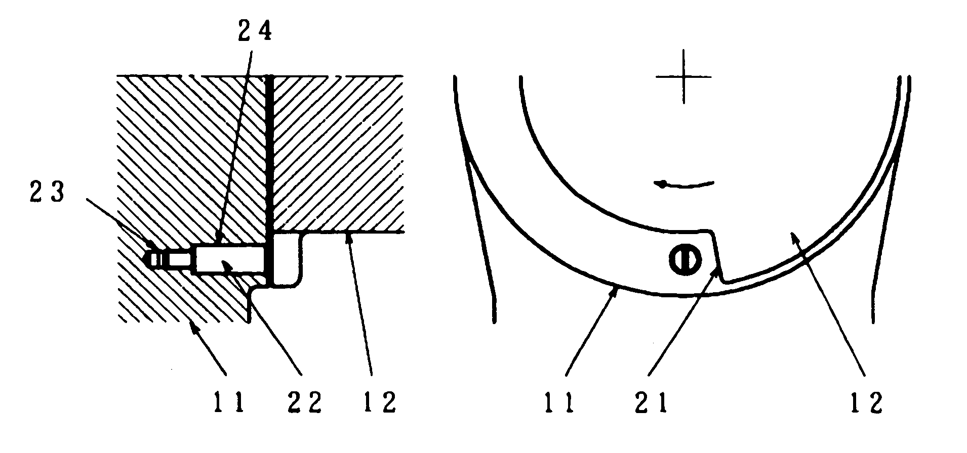
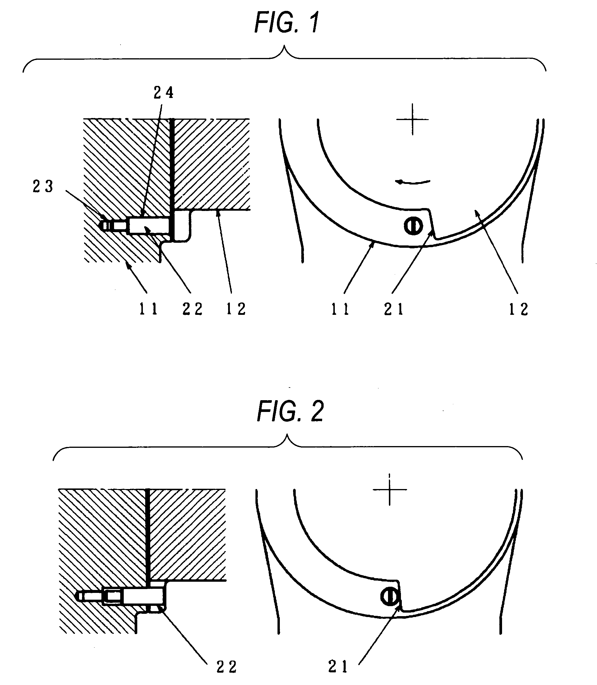
[0019]FIGS. 1, 2 are drawings showing an origin adjustment apparatus portion of an industrial robot according to a first embodiment. In the drawings, a mount portion 23 in which a positioning member 22 is embedded and a guide portion 24 along which the positioning member 22 slide in such a manner as to protrude are provided on a first member 11, and an abutment portion 21, which is brought into abutment with the positioning member 22 when the first member 11 and a second member 12 are made to rotate relatively, is provided on the second member 12.

[0020] Hereinafter, the operation of the industrial robot, which is constructed as described above, will be described. When the industrial robot performs a normal operation, as shown in FIG. 1, the first member 11 and the second member 12 are allowed to perform a free relative rotational operation, and at the same time, the positioning member 22 is embedded in the first member 11 so that a dust proof effect for the positioning member 23 an...

second embodiment

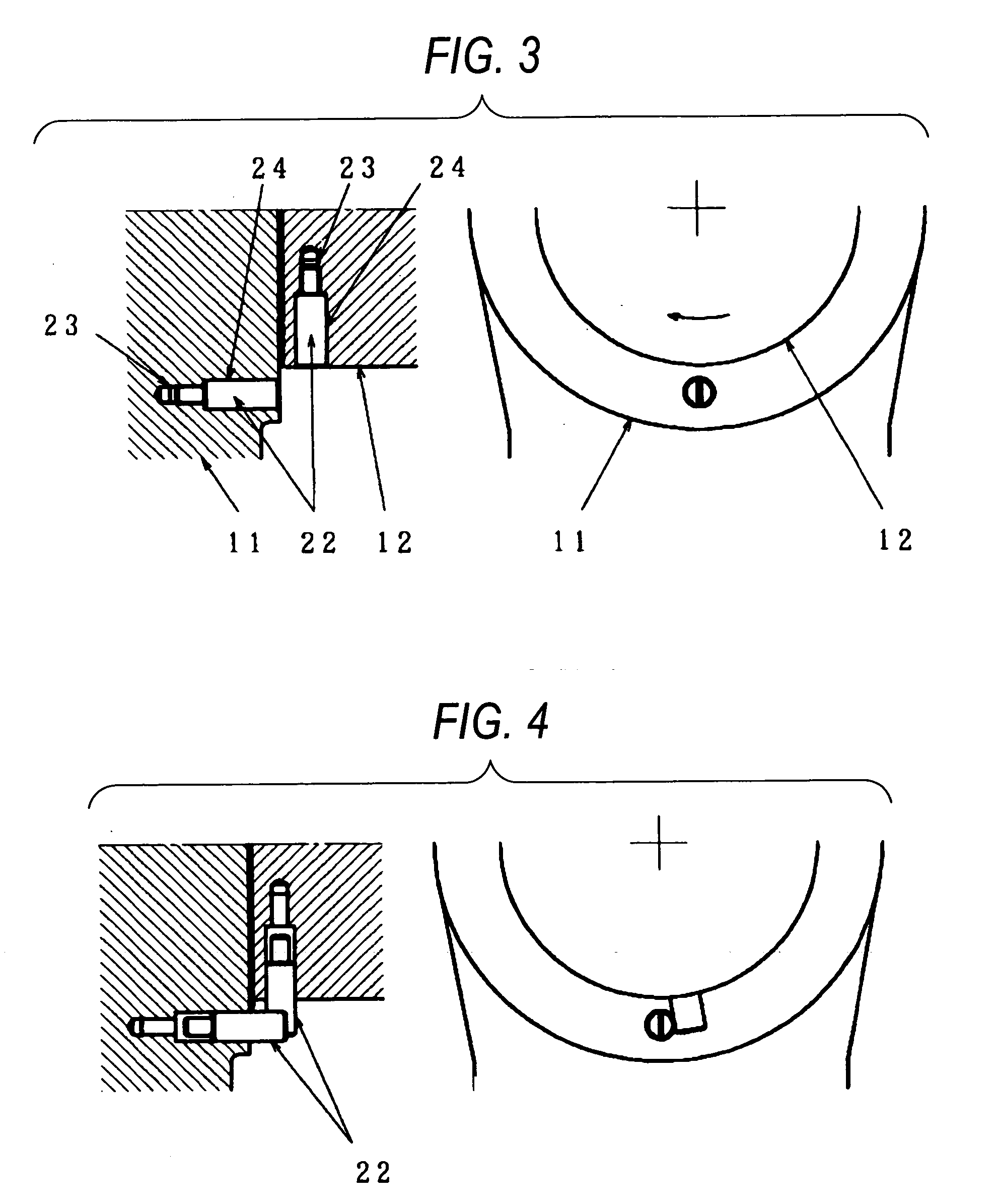
[0024]FIGS. 3, 4 are drawings showing an origin adjustment apparatus portion of an industrial robot according to a second embodiment of the invention. In FIGS. 3, 4, like reference numerals are used as to constituent members like to those described in FIGS. 1 and 2, and the description thereof will be omitted.

[0025] In this embodiment, in place of the abutment portion 21 provided on the second member 12 in the first embodiment, a positioning member 22, which was provided on the first member, and a guide portion 24 along which the positioning member 22 slides in such a manner as to protrude are provided on a second member, whereby an origin adjustment having the same function as that of the first embodiment can be realized by adopting the construction.

[0026] In the first embodiment, the abutment portion 21 is exposed to the outside, and this location needs to be protected against dust in order to perform a highly accurate origin adjustment. In this embodiment, however, the abutment...


PUM


Abstract

In origin adjustment between two members which rotate relatively at a joint of an industrial robot, an origin adjustment apparatus is provided which is inexpensive and highly accurate and which requires extremely few man hours. In addition, an origin adjustment apparatus is provided which is so small in size as to be easily used even on a distal end shaft of a wrist of the robot and which requires no special signal line for origin adjustment. A mount member 23 where a positioning member 22 is embedded and a guide portion 24 along which the positioning member 22 slides in such a manner as to protrude are provided on either one or both of the two members which rotate relatively.

Description

TECHNICAL FIELD [0001] The present invention relates to an industrial robot and more particularly to an origin adjusting apparatus provided at a joint portion of a robot arm. BACKGROUND ART [0002] As an origin adjustment apparatus for a conventional industrial robot, there has existed, for example, a conventional origin adjustment apparatus as shown in FIG. 5. (For example, refer to JP-A-2-180580) [0003] In FIG. 5, a first member 111 and a second member 112 are disposed coaxially and rotate relatively. A stepped portion 113 is formed on a circumferential surface of the first member 111 at an origin corresponding position, and an origin adjustment apparatus is detachably fixed to an origin corresponding position of the second member 112. This origin adjustment apparatus includes a switch holder 115 fixed to the origin corresponding position of the second member 112, a switch means 114 held by the switch holder 15 for generating an origin signal, a linear bearing 116 fixed to the swit...

Claims


Application Information

Patent Timeline
IPC IPC(8): B25J9/10B25J19/00
CPCY10T74/20329B25J9/101
Inventor IWAI, SEIJIHIGASHINO, YUKINORI
Owner PANASONIC CORP
Why Eureka
Try Eureka