Method and apparatus for initiating subsequent exposures based on determination of motion blurring artifacts

a motion blurring and subsequent exposure technology, applied in the field of digital image acquisition system, can solve the problems of requiring extensive computation, unable to a priori know the psf of a general optical system, and unable to solve the problem of a priori,

Inactive Publication Date: 2006-05-11
FOTONATION LTD
View PDF58 Cites 89 Cited by
  • Summary
  • Abstract
  • Description
  • Claims
  • Application Information

AI Technical Summary

Benefits of technology

[0030] In yet another embodiment, the digital processing component analyses the image motion blur in real time based on the captured image and invokes the capture of subsequent image or images when determined that the acquired image is not of acceptable quality due to motion blur.
[0031] Corresponding de-blurring function determining methods are also provided. One or more storage devices are also provided having digital code embedded thereon for programming one or more processors to perform the de-blurring function determining methods.

Problems solved by technology

Moreover, for a physical real life system, an attempt to find a solution may also be exacerbated in the presence of noise or sampling.
The results of such process with no a-priori knowledge of the PSF for a general optical system are far from acceptable and require extensive computation.
However, this requires a special construction of camera and also requires simultaneous capture of images.
Thus this technique is not readily transferable to cheap, mass-market digital cameras.

Method used


Image

  • Method and apparatus for initiating subsequent exposures based on determination of motion blurring artifacts
  • Method and apparatus for initiating subsequent exposures based on determination of motion blurring artifacts
  • Method and apparatus for initiating subsequent exposures based on determination of motion blurring artifacts

Examples


Embodiment Construction

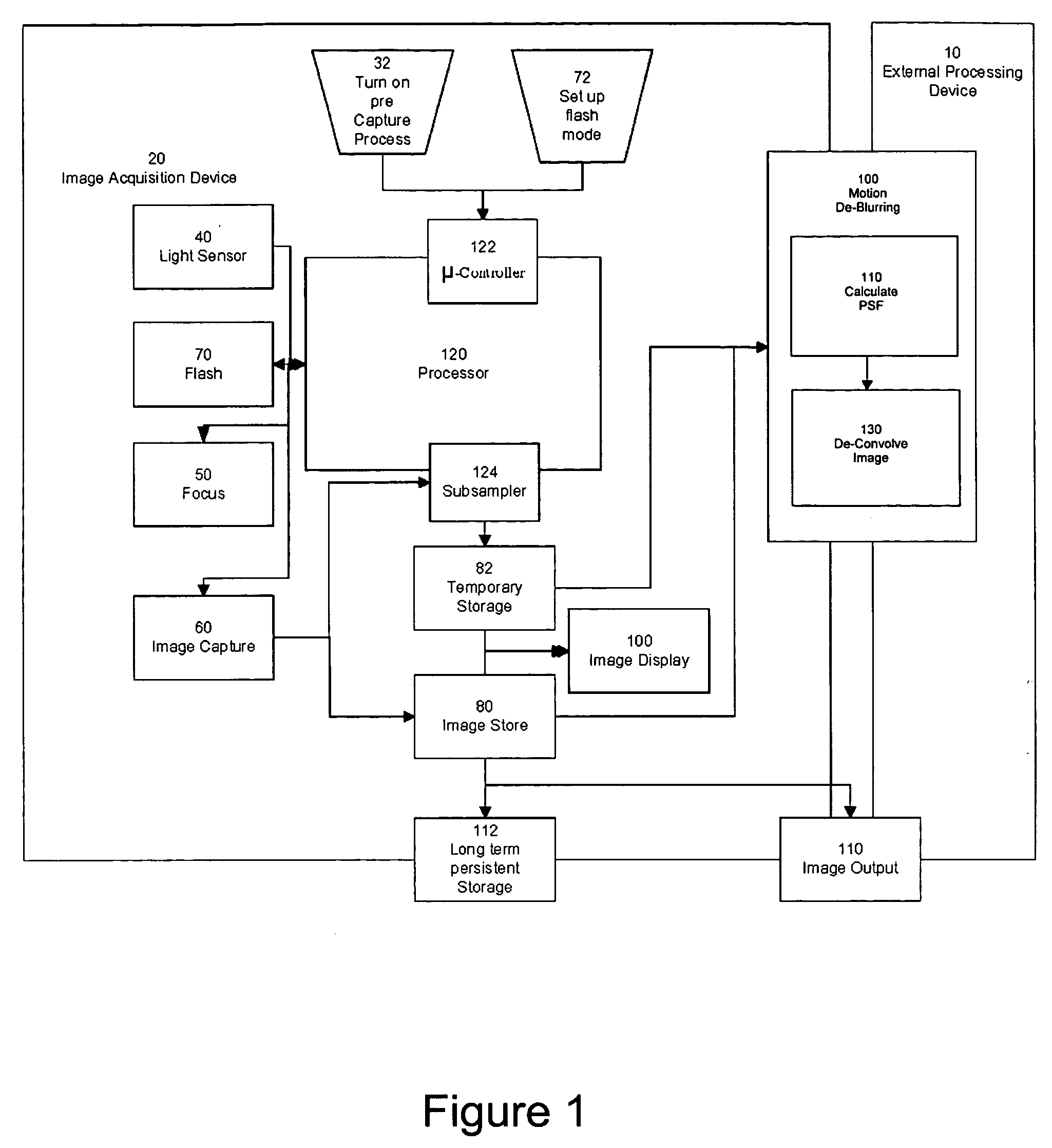
[0039]FIG. 1 shows a block diagram of an image acquisition system such as a digital camera apparatus operating in accordance with the present invention. The digital acquisition device, in this case a portable digital camera 20, includes a processor 120. It can be appreciated that many of the processes implemented in the digital camera may be implemented in or controlled by software operating in a microprocessor (μProc), central processing unit (CPU), controller, digital signal processor (DSP) and / or an application specific integrated circuit (ASIC), collectively depicted as block 120 and termed as “processor”. Generically, all user interface and control of peripheral components such as buttons and display is controlled by a μ-controller 122.

[0040] The processor 120, in response to a user input at 122, such as half pressing a shutter button (pre-capture mode 32), initiates and controls the digital photographic process. Ambient light exposure is determined using light sensor 40 in or...


PUM


Abstract

A digital image acquisition system includes a portable apparatus for capturing digital images and a digital processing component for detecting, analyzing, invoking subsequent image captures and informing the photographer regarding motion blur, and for reducing camera motion blur in an image captured by the apparatus. The digital processing component operates by comparing the image with at least one other image, for example a preview image, of nominally the same scene taken outside the exposure period of the main image. In one embodiment the digital processing component identifies at least one feature in a single preview image which is relatively less blurred than the corresponding feature in the main image, calculates a point spread function (PSF) in respect of such feature, and initiates a subsequent capture if determined that the motion blur exceeds a certain threshold. In another embodiment the digital processing determines the degree of blur by analyzing the motion blur in the captured image itself, and initiates a subsequent capture if determined that the motion blur exceeds a certain threshold. Such real time analysis may use the auto focusing mechanism to qualitatively determine the PSF.

Description

FIELD OF THE INVENTION [0001] This invention relates to a digital image acquisition system comprising a digital processing component for determining motion blurring artifacts, and preferably a camera motion blur function, in a captured digital image. BACKGROUND TO THE INVENTION [0002] Camera motion is dependent on a few parameters. First of all, the exposure speed. The longer the shutter is open, the more likely that movement will be noticed. The second is the focal length of the camera. The longer the lens is, the more noticeable the movement is. A rule of thumb for amateur photographers shooting 35mm film is never to exceed the exposure time beyond the focal length, so that for a 30mm lens, not to shoot slower than 1 / 30th of a second. The third criteria is the subject itself. Flat areas, or low frequency data, is less likely to be degraded as much as high frequency data. [0003] Historically, the problem was addressed by anchoring the camera, such as with the use of a tripod or mon...

Claims


Application Information

Patent Timeline
Patent Type & Authority Applications(United States)
IPC IPC(8): H04N1/23
CPCH04N5/23212H04N5/23248H04N5/23254H04N5/23258H04N5/23264H04N23/673H04N23/6811H04N23/68H04N23/682H04N23/6812H04N23/63
Inventor STEINBERG, ERANCORCORAN, PETERPRILUTSKY, YURY
Owner FOTONATION LTD
Why Eureka
Try Eureka