
Method and apparatus for analyzing performance of a hydraulic pump

a technology of hydraulic pump and performance analysis, applied in the direction of positive displacement liquid engine, machine/engine, instruments, etc., can solve the problems of hydraulic transmission and control system special faults, high cost of unexpected failure of hydraulic system, and most faults in hydraulic-mechanical components

Inactive Publication Date: 2006-03-14
THE BOARD OF TRUSTEES OF THE UNIV OF ILLINOIS
View PDF10 Cites 135 Cited by
  • Summary
  • Abstract
  • Description
  • Claims
  • Application Information

AI Technical Summary

Problems solved by technology

Real-time health assessment for hydraulic pumps is a desired function due to, among other things, the high cost of unexpected failure of hydraulic systems.
Typical hydraulic systems include both hydraulic-mechanical and electronic components, but most faults occur in the hydraulic-mechanical components.
Furthermore, a hydraulic transmission and control system has its own special faults, such as oil pollution, leakage, air erosion, hydraulic blocking, pipe resonance, distortion of electrical signal, noise, and system surging.
However, because these parameters are indirect measures of hydraulic system operating conditions, and due to the multiple motion forms of hydraulic-mechanical components and the interference of multiple components via the hydraulic lines, a more complicated process is required to use these indirect parameters to monitor a state of the hydraulic system sensitively and accurately.
In piston-type hydraulic pumps, for example, common faults include, but are not limited to, worn pistons, swash plates, and distributing discs, bearing and spring failures, and loose piston shoes.
In addition, there are other noise sources, such as air erosion, hydraulic blocking, pipe resonance and leakage, etc. reflected in the pump discharge pressure.
These noises normally result in a very low signal-to-noise ratio in the pump discharge pressure signals.
Conventional health diagnosis methods, such as limit checking, spectrum analysis, and logic reasoning, require a distinguishable feature signal to detect faults, but these methods heretofore have not been sensitive or robust enough to reliably detect pump faults.

Method used


Image

  • Method and apparatus for analyzing performance of a hydraulic pump
  • Method and apparatus for analyzing performance of a hydraulic pump
  • Method and apparatus for analyzing performance of a hydraulic pump

Examples


Embodiment Construction

[0017]Fault diagnosis methods based on the vibration signals measured from the pump shell result in significant vibration effects, including environmental effects, which influence the quality of the obtained signals. More particularly, such signals consist of a series of harmonic frequencies and contain high background noises, making it difficult to distinguish feature signals of pump faults from the vibration signals. Furthermore, these methods are normally based on spectrum analysis that uses Fourier transform (FT), short-time Fourier transform (STFT), and / or time sequence analysis (TSA). Because these methods process signals in the frequency domain or time domain signals alone, they have limitations in practical applications.

[0018]The present invention provides, among other things, a fault diagnosis method and apparatus that assesses, in real-time, pump health conditions and fault symptoms based on pump discharge pressure. Accordingly, preferred embodiments of the present inventi...


PUM


Abstract

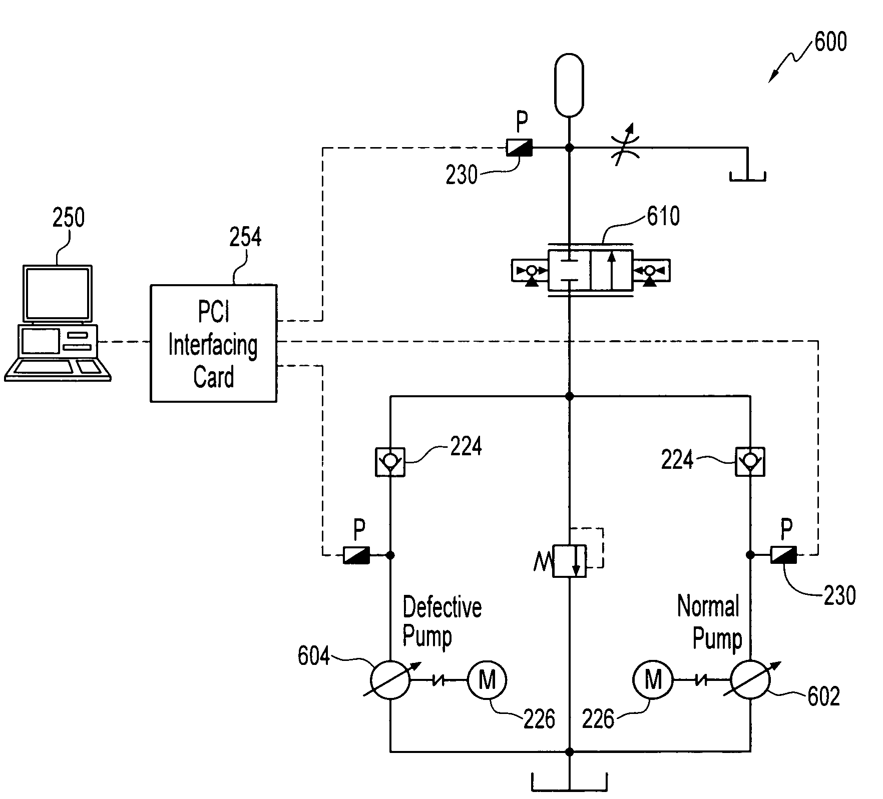
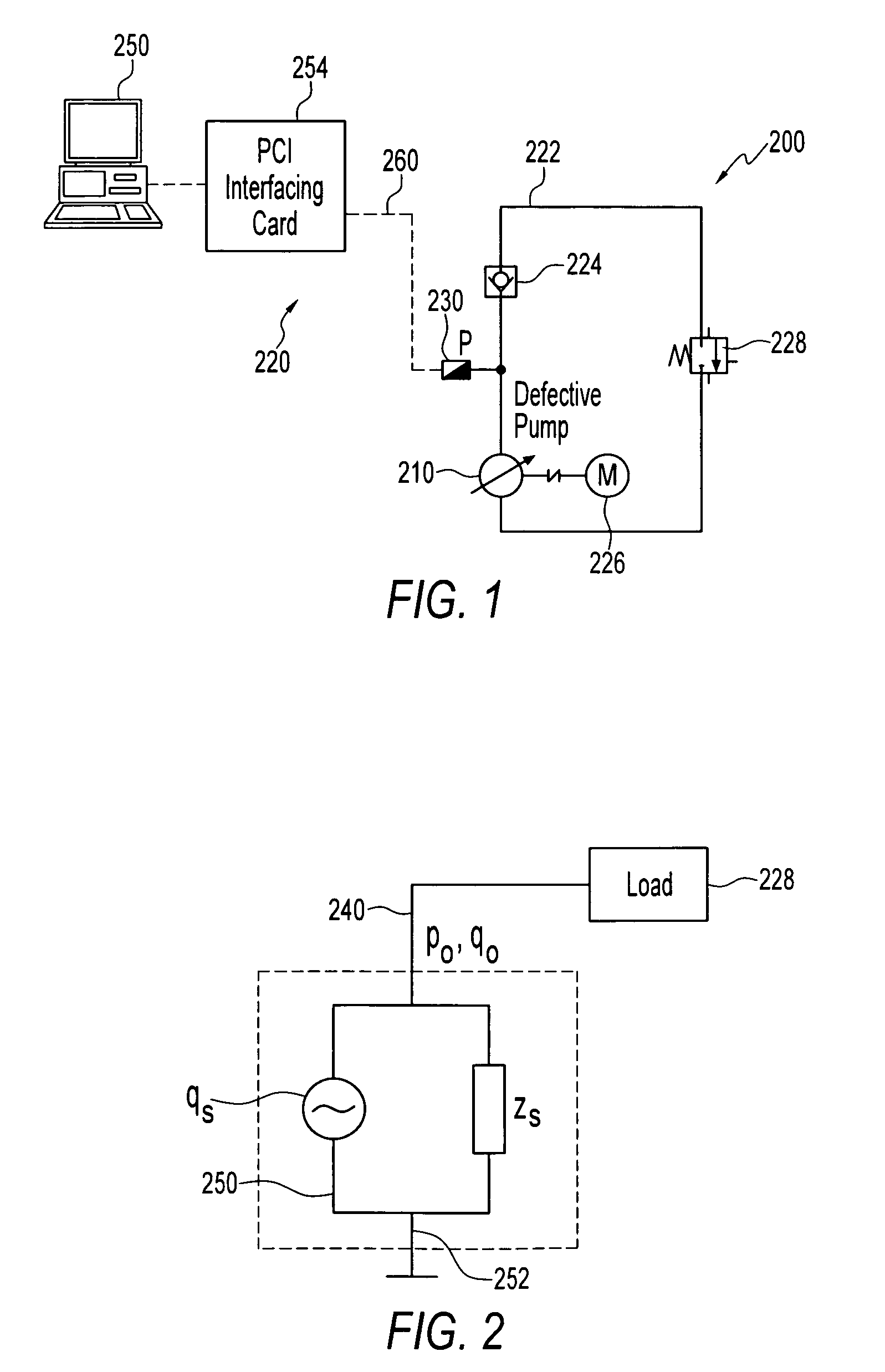
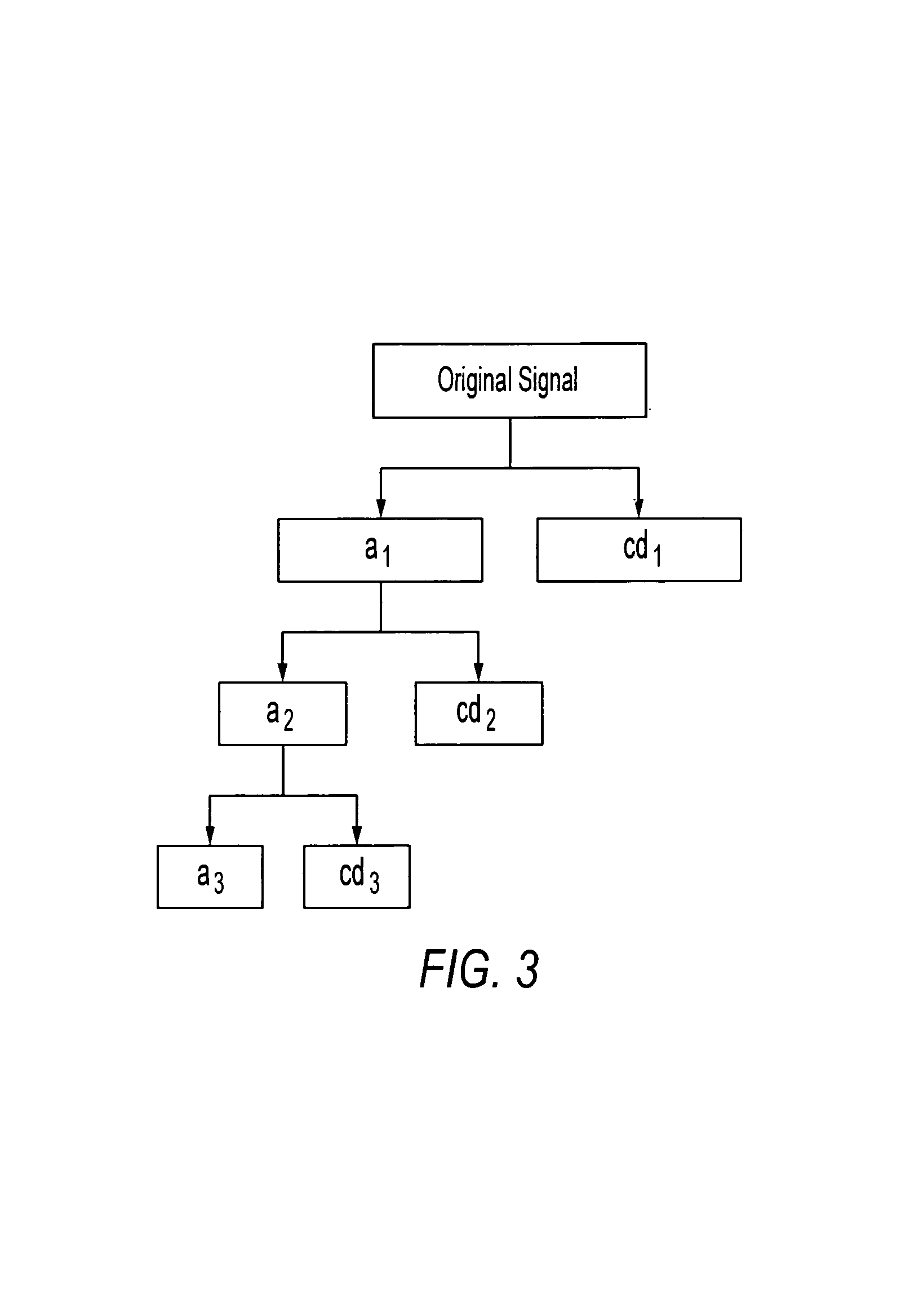
A method and apparatus for analyzing a hydraulic pump in real-time. A pressure signal is provided representing a discharge pressure of the hydraulic pump, and the pressure signal is decomposed into a plurality of levels. Each of the plurality of levels has at least one frequency band. A feature pressure signal is located in at least one of the frequency bands and compared to a reference wavelet to determine if a fault exists in the hydraulic pump and / or a type of defect in the hydraulic pump.

Description

PRIORITY CLAIM[0001]This application claims priority of U.S. Provisional Application Ser. No. 60 / 413,328, filed Sep. 25, 2002.FIELD OF THE INVENTION[0002]The present invention relates generally to the field of hydraulic system analysis.BACKGROUND OF THE INVENTION[0003]Real-time health assessment for hydraulic pumps is a desired function due to, among other things, the high cost of unexpected failure of hydraulic systems. Typical hydraulic systems include both hydraulic-mechanical and electronic components, but most faults occur in the hydraulic-mechanical components. Common hydraulic system faults include, but are not limited to distortion, stress rupture, erosion, rubbing abrasion, impacting rupture, heat stress, and hot distortion. Furthermore, a hydraulic transmission and control system has its own special faults, such as oil pollution, leakage, air erosion, hydraulic blocking, pipe resonance, distortion of electrical signal, noise, and system surging.[0004]Many existing fault di...

Claims


Application Information

Patent Timeline
IPC IPC(8): G06F11/30
CPCF02M65/003
Inventor ZHANG, QINGAO, YINGJIEKONG, XIANGDONG
Owner THE BOARD OF TRUSTEES OF THE UNIV OF ILLINOIS
Learn More