
Methods and systems for rapid detection of concealed objects using fluorescence

a technology of fluorescence and concealed objects, applied in the field of xray based methods and systems, to achieve the effect of accurate identification of nature and increased throughpu

Inactive Publication Date: 2006-05-11
RAPISCAN SYST INC (US)
View PDF9 Cites 117 Cited by
  • Summary
  • Abstract
  • Description
  • Claims
  • Application Information

AI Technical Summary

Benefits of technology

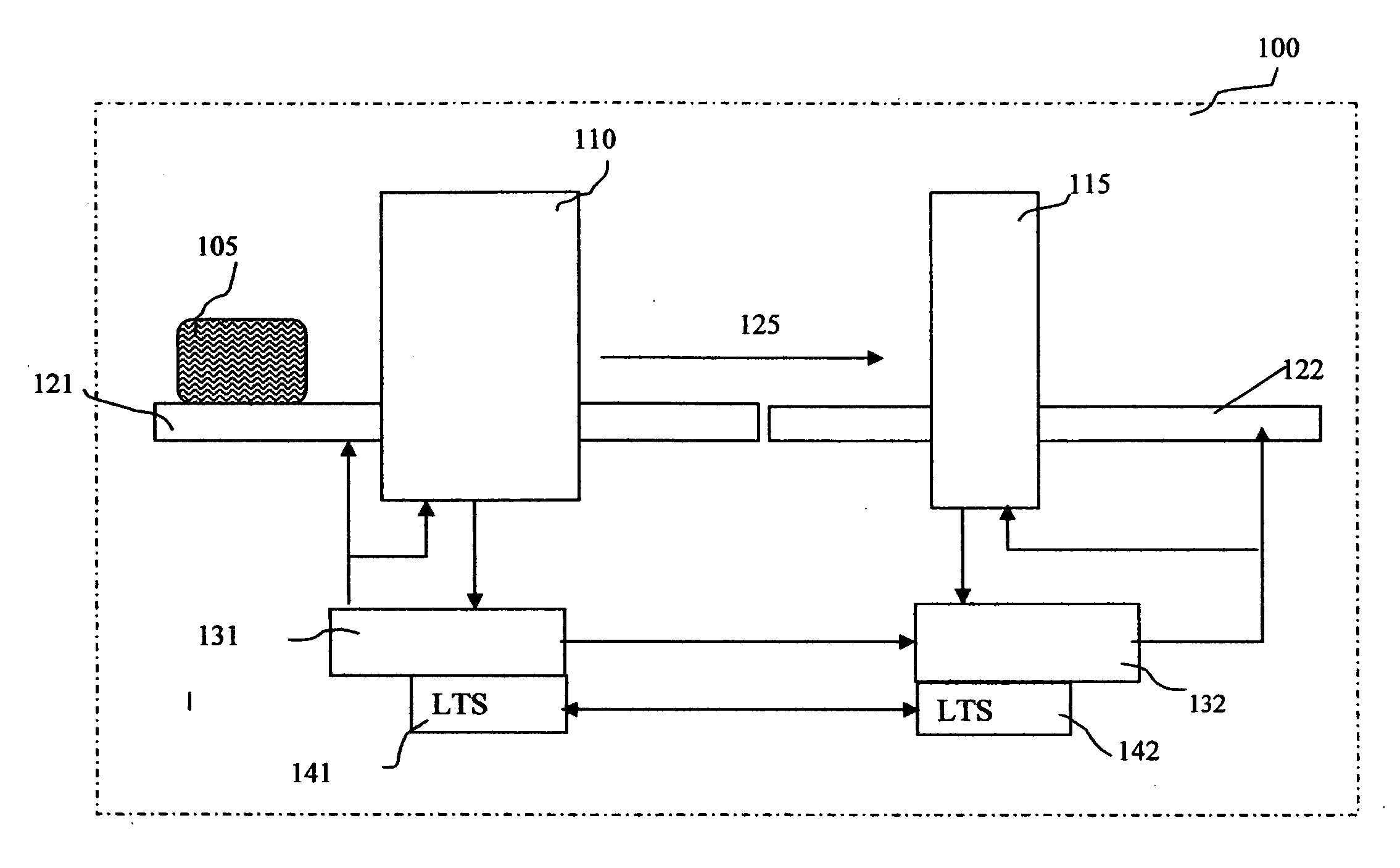
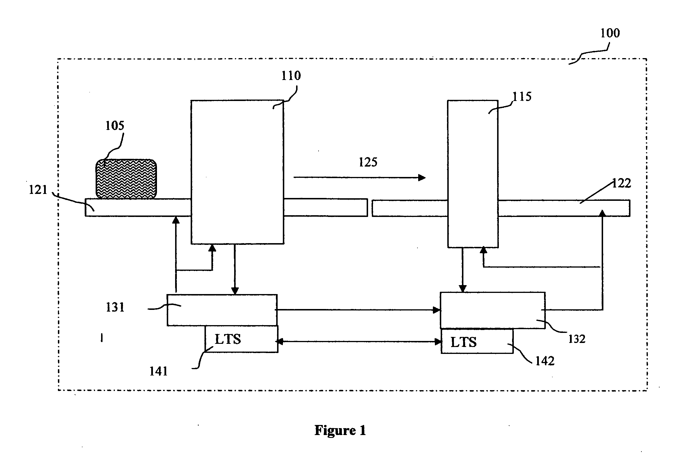
The present invention provides an improved scanning process for identifying threats in containers. The process includes a first stage inspection system that generates a first set of data, which is then processed using a data processing system to identify target regions. The system also includes a conveyor for positioning the container between the first and second stages of inspection. The second stage inspection system generates a second set of data with an X-ray signature characteristic and / or fluorescence signature characteristic of the material in the inspection region. The invention also provides a single stage inspection system and a device for identifying target material within a target object. The invention is cost-effective and utilizes standard industrial components.

Problems solved by technology

These objects may be considered threats, such as an illegal drug, an explosive material, or a weapon.

Method used


Image

  • Methods and systems for rapid detection of concealed objects using fluorescence
  • Methods and systems for rapid detection of concealed objects using fluorescence
  • Methods and systems for rapid detection of concealed objects using fluorescence

Examples


second embodiment

[0103] In a second embodiment, the transmission detector array functions as an imaging detector to provide precise attenuation data for certain areas in containers, like container wall areas, where contraband can be hidden. When the circular beam is centered on an edge of a container, the edge of the container can be imaged in good detail, and can help analyze the edges for concealed threats.

third embodiment

[0104] In a third embodiment, transmission detector measurements can be used to determine whether the inspection region is, in fact, the same target region previously identified in the first stage scan. If the transmission data correlates with X-ray characteristics different than those obtained in the first stage scan, the relative positioning of the second stage scanning system and the object under inspection may be modified until the transmission data correlates with the same material characteristics that was identified in the first stage scan.

fourth embodiment

[0105] In a fourth embodiment, transmission detector data are also being used to simplify the algorithm-training procedure of the system, as described below, in particular the collection of threat material properties with irregularly shaped threat samples, like sticks of dynamite.

[0106] It should be noted that it would appear because the scatter radiation path and transmission path differ downstream from the scatter volume, there would be inconsistencies in the data when scatter and transmission data are combined. This inconsistency is one example of a number of partial volume effects, solutions for which are addressed herein. However, the inconsistencies are not significant and can be tolerated without encountering significant performance degradation of the system as a whole. As shown, FIG. 5 is not an isometric schematic and, in reality, the scatter angle is preferably about 3 degrees, and the real path differences are comparatively smaller.

[0107] As previously discussed, the sec...


PUM

PropertyMeasurementUnit
weightaaaaaaaaaa
thickaaaaaaaaaa
atomic numberaaaaaaaaaa

Abstract

This invention is directed towards finding, locating, and confirming threat items and substances. The inspection system is designed to detect objects that are made from, but not limited to, special nuclear materials (“SNM”) and / or high atomic number materials. The system employs advanced image processing techniques to analyze images of an object under inspection (“OUI”), which includes, but is not limited to baggage, parcels, vehicles and cargo, and fluorescence detection.

Description

CROSS-REFERENCE TO RELATED APPLICATIONS [0001] The present invention relies on U.S. Provisional Patent No. 60 / 619,339, filed on Oct. 15, 2005, for priority and is a continuation-in-part of co-pending U.S. patent application Ser. No. 10 / 910,250, filed on Aug. 3, 2004 which is a continuation-in-part of co-pending U.S. patent application Ser. No. 10 / 662,778, filed on Sep. 15, 2003.FIELD OF THE INVENTION [0002] The present invention relates generally to X-ray based methods and systems for detection of concealed threats, and threat resolution, and more specifically to improved methods and systems, for the detection of concealed threats, such as explosives. Optionally, the present invention uses a multiple stage scanning system to process luggage for the detection of concealed threats. BACKGROUND OF THE INVENTION [0003] Conventional X-ray systems produce radiographic projection images, which are then interpreted by an operator. These radiographs are often difficult to interpret because ob...

Claims


Application Information

Patent Timeline
Patent Type & Authority Applications(United States)
IPC IPC(8): G01N23/04
CPCG01N23/04
Inventor PESCHMANN, KRISTIAN R.
Owner RAPISCAN SYST INC (US)
Learn More