Surgical clip and method for making same

a technology of surgical clips and clamps, applied in the field of surgical clips or clamps, can solve the problems of time-consuming and costly process, high cost of metal clips and clamps, and inability to meet the needs of patients, and achieve the effects of convenient cleaning and sterilization, high automation, and cost-effectiveness

Inactive Publication Date: 2006-05-11
APPL MEDICAL RESOURCES CORP
View PDF33 Cites 36 Cited by
  • Summary
  • Abstract
  • Description
  • Claims
  • Application Information

AI Technical Summary

Benefits of technology

[0010] The single-wire construction of the improved clamp may be achieved through programmed wire forming, which is highly automated and cost effective. The clamp of the invention is easy to clean and sterilize since there are no rivets or joined components.

Problems solved by technology

Currently, it is very costly to make metal clips and clamps, especially the small clips and clamps that require great precision in the manufacturing process.
Moreover, in order to reuse these clips and clamps, they have to be carefully cleaned and stored in specialized containers, the process of which is time consuming and costly.
The plastic clip or clamp, however, requires a different construction and a similarly sized clip or clamp does not provide the same traction or clamping force as its metal counterpart.
As a consequence, larger and bulkier plastic clips or clamps have to be used in place of the metal devices.

Method used


Image

  • Surgical clip and method for making same
  • Surgical clip and method for making same
  • Surgical clip and method for making same

Examples


Embodiment Construction

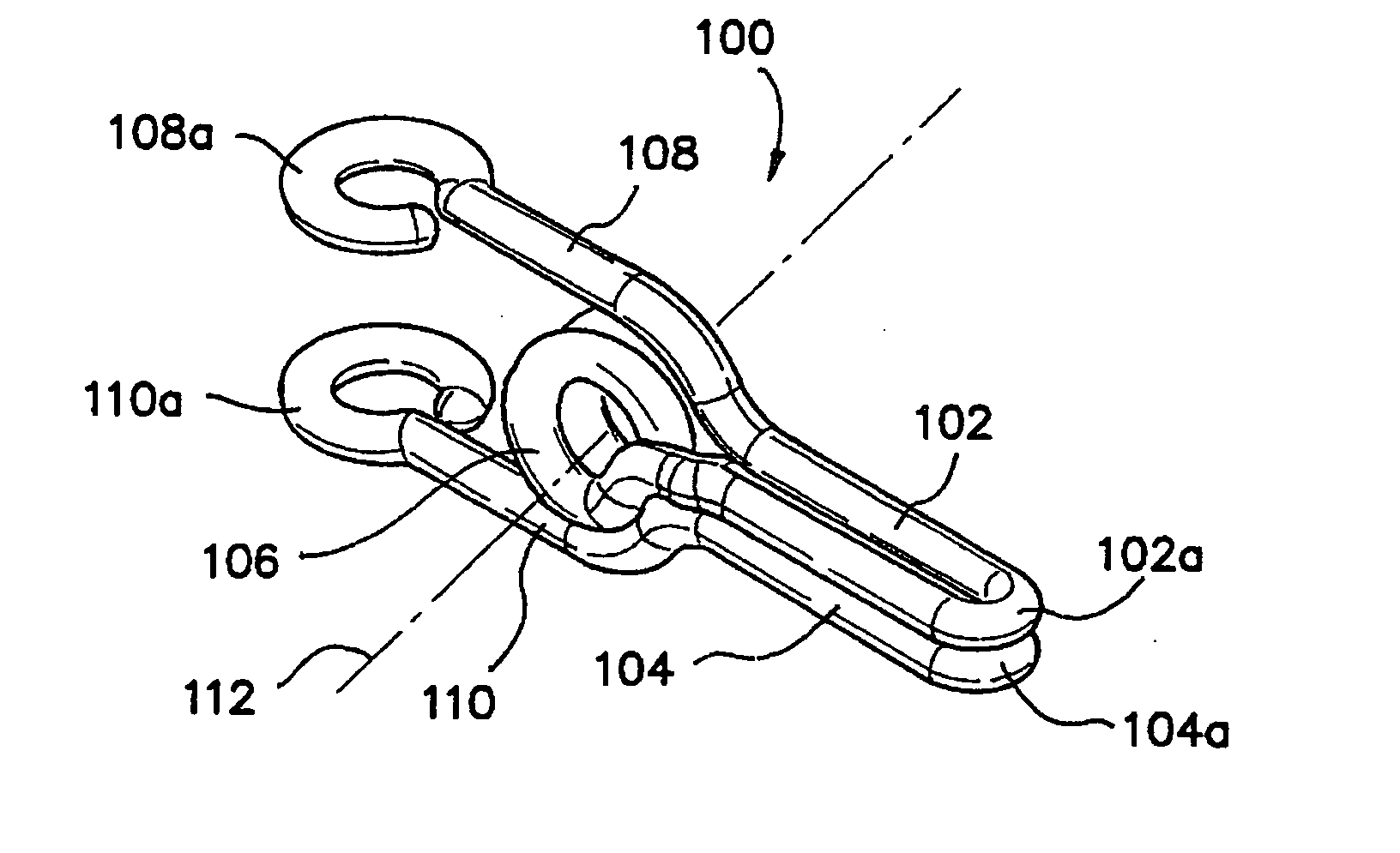
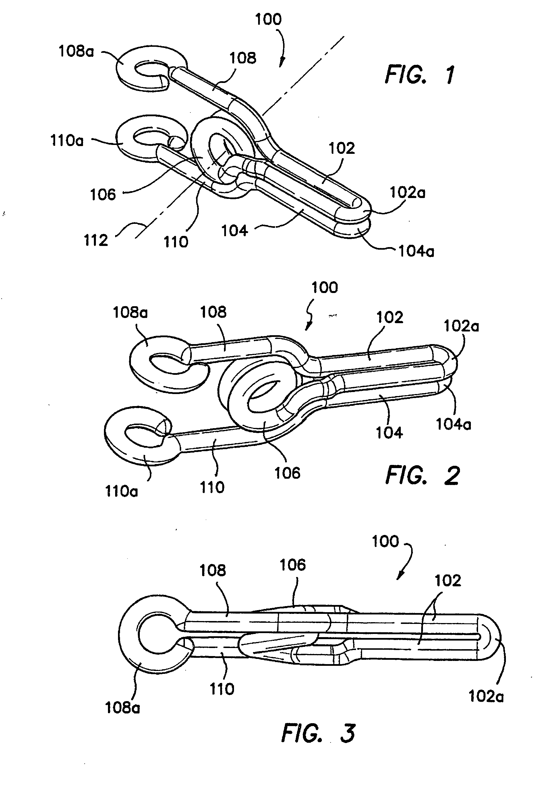
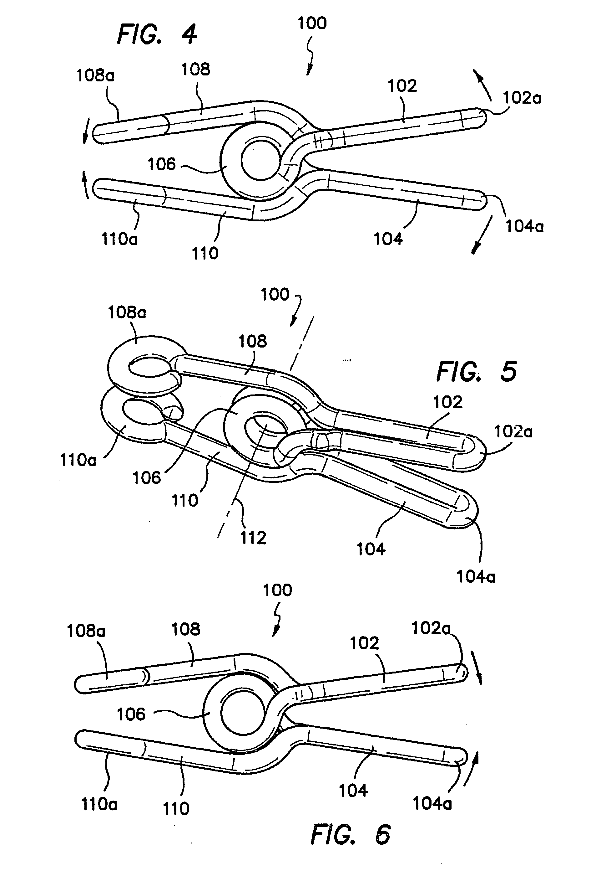
[0034]FIGS. 1-3 illustrate a surgical clamp 100 in accordance with the first embodiment of the invention. Surgical clamp 100 is unique in that it is formed from a single piece of wire and includes a first jaw portion 102, a second jaw portion 104, a first handle portion 108, a second handle portion 110 and a central coil or tensioning device 106 operatively connected to the first jaw portion 102, second jaw portion 104, first handle portion 108 and second handle portion 110. The central coil or tensioning device 106 has a longitudinal axis 112 and comprises one or more turns. The handle portions 108 and 110 may include ring-shaped distal tips 108a and 110a, respectively, that further enhance grip. The clamp 100 operates by squeezing together the handle portions 108 and 110 about the axis 112 to open the jaw portions 102 and 104, respectively, placing the jaw portions 102 and 104 around a target body conduit, and slowly letting go of the handle portions 108 and 110 to allow the jaw p...


PUM


Abstract

An improved clip or clamp is provided having a one-piece wire-form construction that is suited for rapid and repeatable manufacture. The clamp, which may be disposable or reusable, includes a first jaw portion, a second jaw portion, a first handle portion, a second handle portion and a central coil or tensioning device, all of which are formed from a single piece of wire. The central coil or tensioning device comprises one or more turns. The handle portions may include ring-shaped distal ends that further enhance grip. The jaw portions may be shaped, curved, bent or otherwise configured to provide access to specific areas of a procedure. The clamp may be coated with a material providing improved traction and padding. In a method of the invention, a single wire is wound at least one turn forming the central coil and two extensions. A first extension of the wire is formed into the first jaw portion by bending back on itself, the first extension is then returned to the central coil where it is formed to rest upon an outer surface of the central coil. The bent first extension, which now extends rearward in a direction opposite to the direction of the first jaw portion, is then bent again forming the first handle portion. A second extension is similarly bent to form the second jaw portion and the second handle portion. The single-wire construction of the clamp may be achieved through programmed wire forming. In another aspect of the invention, a plurality of clamps may be placed upon a traction rod made from a metal or plastic material to align two or more stump portions of a severed vessel or tissue for reconnection or anastomosis.

Description

[0001] This is a non-provisional application claiming the priority of provisional application Ser. No. 60 / 448,022, filed on Feb. 18, 2003, entitled “Surgical Clip and Method for Making Same,” which is fully incorporated herein by reference.BACKGROUND OF THE INVENTION [0002] 1. Field of the Invention [0003] This invention generally relates to surgical clips and clamps and, more specifically, to a surgical clip or clamp having a one-piece wire-form construction suited for rapid and low cost manufacture. [0004] 2. Discussion of the Prior Art [0005] Clips and clamps are commonly used in surgical procedures to interrupt or inhibit fluid flow in body conduits such as arteries, veins and ducts. These clips and clamps may be disposable or reusable. The disposable clips and clamps are typically made of plastic while the reusable clips and clamps are generally made of metal. These devices usually include extension or compression springs for biasing the opposed jaws to a closed position. In pa...

Claims


Application Information

Patent Timeline
Patent Type & Authority Applications(United States)
IPC IPC(8): A61B17/08A61B
CPCA61B17/083A61B17/1227A61B2017/00946A61B2017/1103A61B2017/1107A61B2017/1135A61B17/08
Inventor HART, CHARLES C.KAHLE, HENRYSAKAKINE, GHASSAN
Owner APPL MEDICAL RESOURCES CORP
Why Eureka
Try Eureka