
Bait-casting rod handle

a fishing rod and handle technology, applied in the field of fishing rods with a pistol grip, can solve the problems of cumbersome and distracting form of stationary attachment to the non-dominant arm, exert a significant strain on the wrist of the fisherman, etc., and achieve excellent control of the rod twist, increased rod leverage, and improved rod control

Inactive Publication Date: 2006-05-18
LACOSTE BRIAN O
View PDF34 Cites 9 Cited by
  • Summary
  • Abstract
  • Description
  • Claims
  • Application Information

AI Technical Summary

Benefits of technology

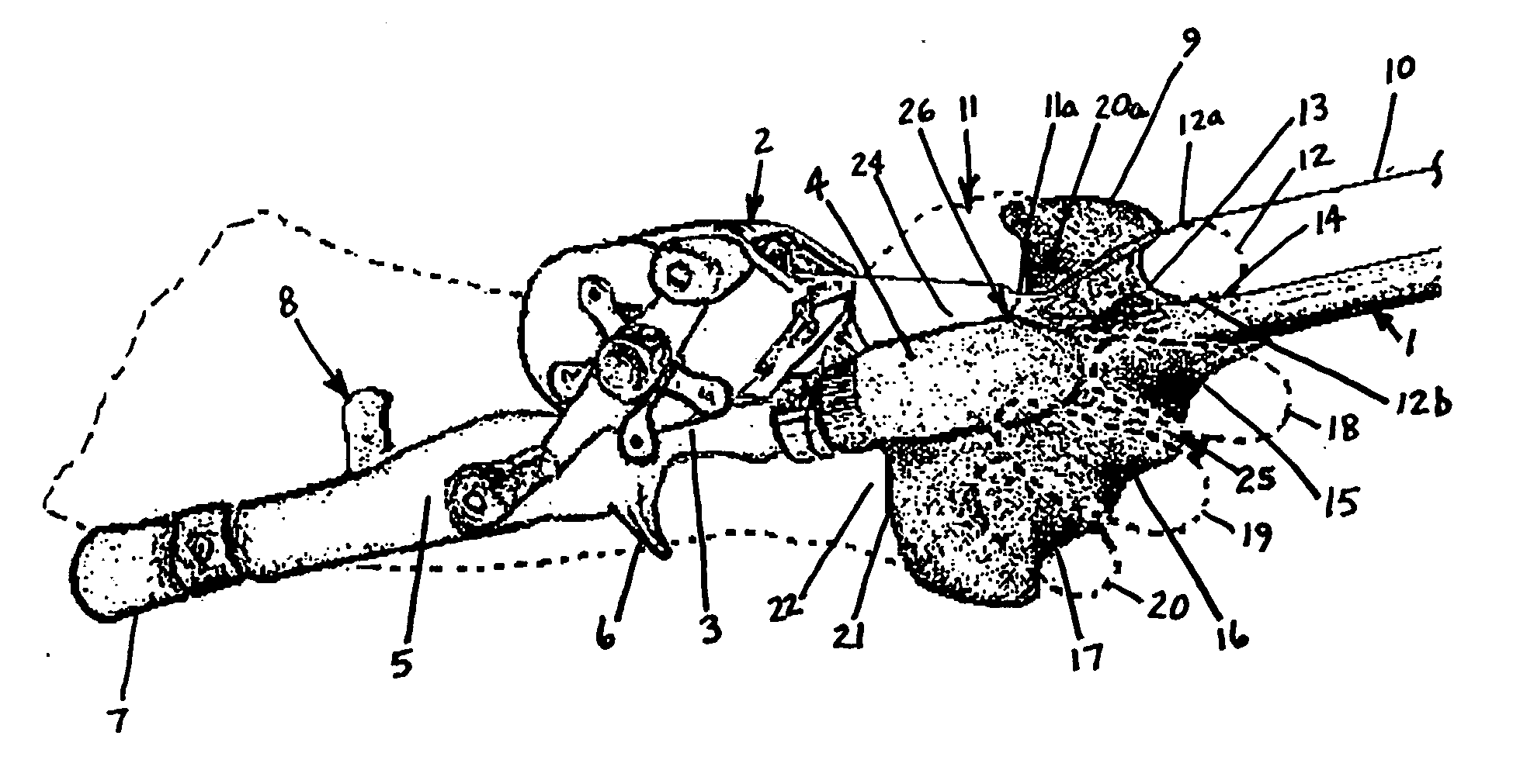
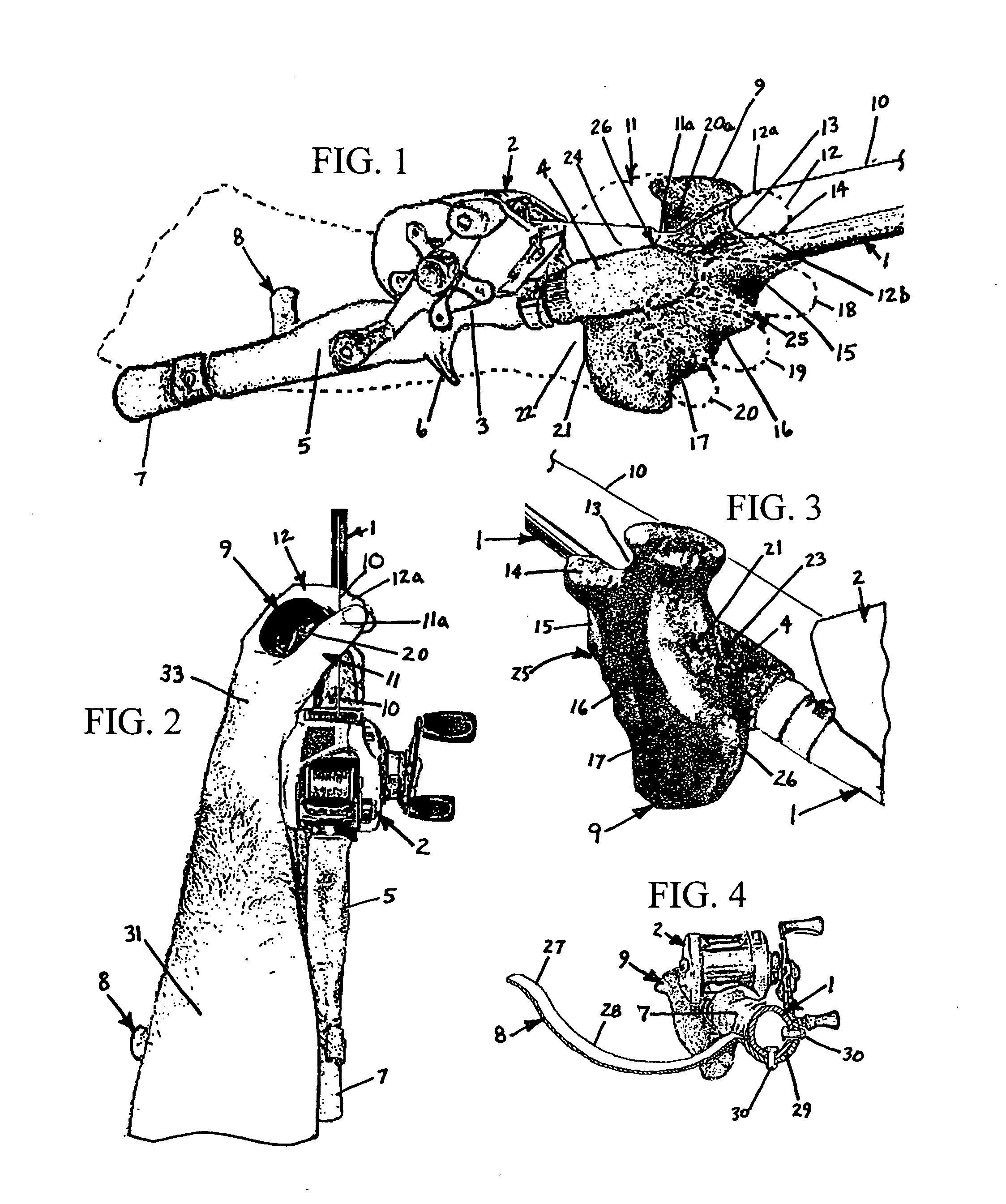
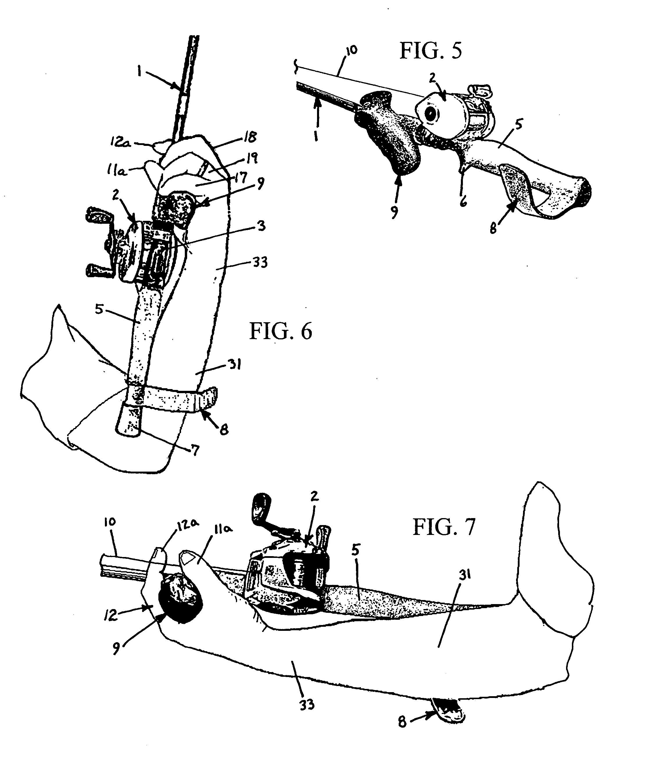
[0008] The inventive preferred design provides increased rod leverage and excellent control of rod twist over conventional, straight-handled bait-casting fishing rods. The rear forearm cradle rests on or near the butt end of the rod and when combined with the ergonomic pistol-grip type handle located ahead of the reel, features a novel means of improved rod control while requiring the use of only one arm for rod support and use. Additionally, the design combination provides the user with a comfortable fulcrum point near the rod's center of gravity, which repeatably locates the user's index finger and thumb in close proximity to the fishing line ahead of the reel to afford superior sensitivity to fluctuations in line tension. The slight offset design of the forward grip ensures the rod's effectiveness, regardless of the style or design of bait-casting reel used in conjunction with the rod and provides a comfortable location of the fisherman's forearm substantially parallel to the rod. Furthermore, the design combination incorporates a conventional second grip behind the reel to be used during orthodox casting operations.

Problems solved by technology

As a consequence, without the application of some form of rigid support structure external to the fisherman's person, holding the rod using one hand while attempting to land even small fish can exert a significant strain on the fisherman's wrist.
Since the rod is typically repeatedly swapped from hand to hand while fishing, any form of stationary attachment to the non-dominant arm proves cumbersome and distracting.

Method used


Image

  • Bait-casting rod handle
  • Bait-casting rod handle
  • Bait-casting rod handle

Examples


Embodiment Construction

[0021] Referring now to the drawings, wherein like reference numerals designate identical or corresponding parts throughout the several views shown, FIG. 1 illustrates a conventional rod and reel assembly which has been modified to contain the fundamental components of a preferred embodiment of the present design. The conventional rod and reel assembly includes a conventional flexible member or rod 1, a bait-casting reel 2, mounted in a reel seat 3, a front grip 4, a rear casting handle 5 on the rod 1, an underside trigger support 6, and a rear handle extension or butt 7. Although many variations of the conventional rod and reel assembly exist, the design of this invention is applicable to all such assemblies, with minor, if any, alterations. The fundamental components of the present design are the rear forearm cradle 8 and the forward grip 9, which can be incorporated individually or collectively on the rod 1. The forearm cradle 8 is typically constructed of a resilient material su...


PUM


Abstract

A handle for bait-casting type fishing rods, with a preferred embodiment including a single-piece, lightweight, contoured pistol-grip type handle located on the rod ahead of the reel to afford the user exceptional fishing sensitivity due to direct finger contact with the fishing line extending from the reel. The handle also affords good control over rod twist and facilitates a more positive grip than conventional grasping of the rod during reeling. Also included is a rear forearm cradle that acts as a lever point which, when combined with the pistol-grip type handle, provides exceptional control of rod tip motions, useful during hook sets and while counteracting the pull of a fish. A preferred embodiment includes the pistol grip handle and forearm cradle features, either or both of which can be retrofitted to or incorporated into conventional casting rod handle designs that may include trigger grips and attachment mechanisms for securing a reel in place. Because of the two control points provided by the forward pistol-grip handle and rear forearm cradle, this embodiment facilitates use of only one arm to hold and support the fishing rod during reeling.

Description

CROSS-REFERENCE TO RELATED APPLICATIONS [0001] This application claims the benefit of and incorporates by reference prior filed copending U.S. Provisional Application Ser. No. 60 / 628,154, Filed Nov. 16, 2004.FIELD OF THE INVENTION [0002] The present invention relates to bait-casting type fishing rods and more specifically, provides a contoured pistol-grip type handle located on the rod ahead of the reel to afford the user exceptional fishing sensitivity due to direct finger contact with the fishing line. The handle also affords good control over rod twist and provides the fisherman more command of the rod than is possible when conventionally grasping the rod directly around the rod axis during reeling. In addition, a rear forearm cradle on or near the butt of the rod acts as a lever point and when combined in a preferred embodiment with the forward fulcrum point created by the handle, provides exceptional control of rod tip motions, useful during hook sets and while counteracting th...

Claims


Application Information

Patent Timeline
Patent Type & Authority Applications(United States)
IPC IPC(8): A01K97/10A01K87/00A01K87/08
CPCA01K87/08
Inventor LACOSTE, BRIAN O.
Owner LACOSTE BRIAN O
Learn More