Brittle material substrate scribing device and scribing method, and automatic analysis line

Inactive Publication Date: 2006-05-18
MITSUBOSHI DIAMOND IND CO LTD
View PDF9 Cites 33 Cited by
  • Summary
  • Abstract
  • Description
  • Claims
  • Application Information

AI Technical Summary

Problems solved by technology

If the glass substrate on which the blind crack BC has not been normally formed is supplied to the subsequent break step, the glass substrate is not broken along the blind crack BC, which may lead to damage of the glass substrate.
When damaged in the break step, the glass substrate cannot be used as a component of an FPD, resulting in loss of economical efficiency as well as deteriorated production efficiency of the FPD.
Further, the damage of the glass substrate might cause damage of a device for breaking a glass substrate itself.
Howev

Method used


Image

  • Brittle material substrate scribing device and scribing method, and automatic analysis line
  • Brittle material substrate scribing device and scribing method, and automatic analysis line
  • Brittle material substrate scribing device and scribing method, and automatic analysis line

Examples


Embodiment Construction

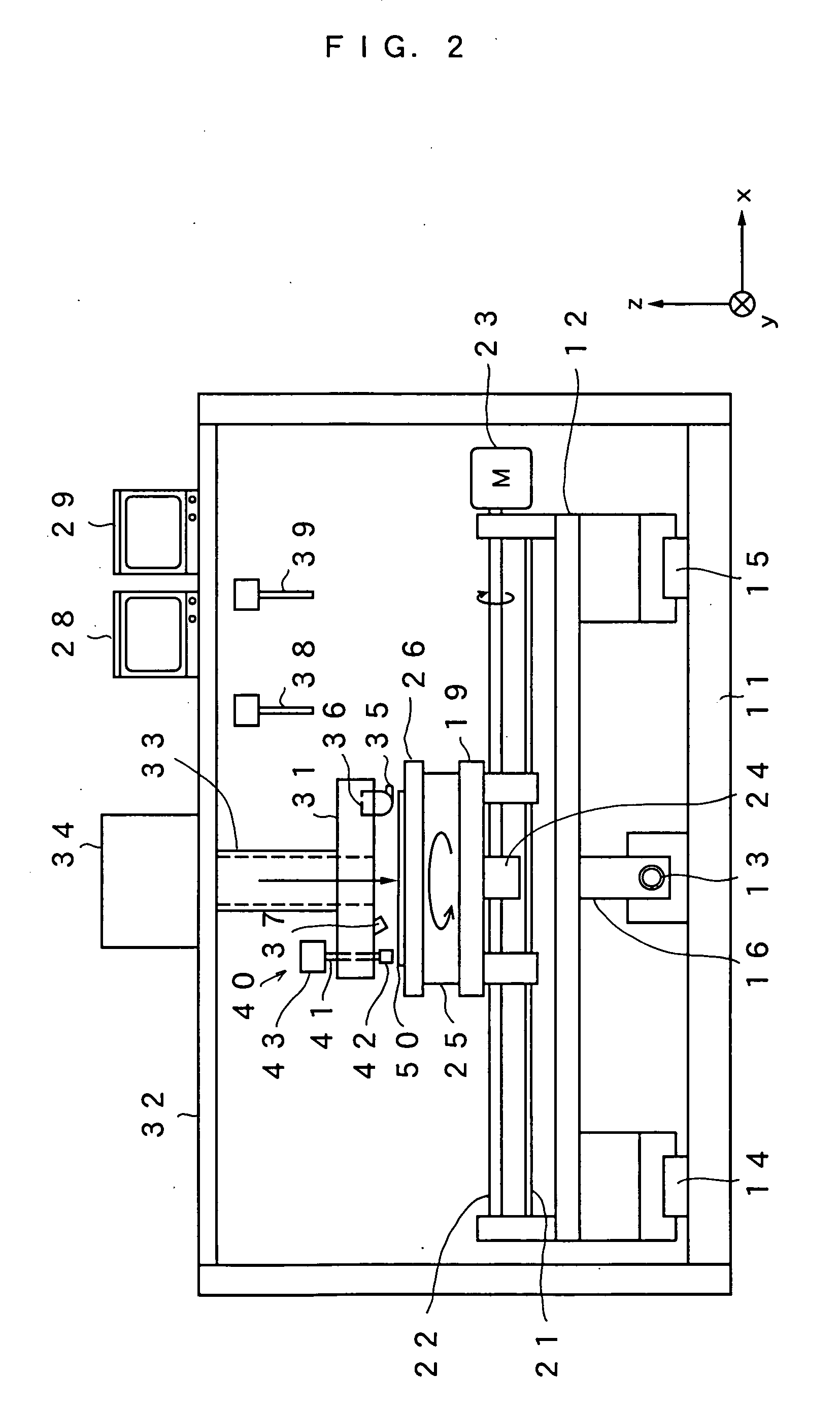
[0028] In the following, devices for scribing a brittle material substrate according to embodiments of the present invention will be described based on drawings. The scribing device is used in one of scribe steps for breaking a glass substrate to be used for an FPD, for example. FIG. 2 is a schematic constitutional view which shows an embodiment of the present invention. This scribing device comprises a slide table 12, which reciprocates along a predetermined horizontal direction (Y direction), on a horizontal base 11.

[0029] The slide table 12 is slidably supported by a pair of guide rails 14 and 15, which are arranged in parallel along an upper surface of the base 11, in a horizontal state along each of the guide rails 14 and 15. A ball screw 13 is provided in the middle of the guide rails 14 and 15 so as to rotate in parallel with each of the guide rails 14 and 15 by means of a motor (not shown). The ball screw 13 is rotatable forward and rearward by means of the motor (not shown...


PUM

PropertyMeasurementUnit
Temperatureaaaaaaaaaa
Brittlenessaaaaaaaaaa
Diffuse reflection IR spectrumaaaaaaaaaa

Abstract

Along a region where a scribe line is formed on a surface of a glass substrate 50, a laser spot is continuously applied for heating at a temperature lower than a softening point of the glass substrate 50, and a region in the vicinity of the heated region is cooled. In this manner, a blind crack is formed along a line to be scribed. A detection unit 40 applies light to the blind crack, immediately after formed in the vicinity of to a cooling spot, through an optical fiber 41. When the blind crack has been formed, part of the light is obtained in the optical fiber 41 because of diffuse reflection. Therefore, detection of the level of this reflected light allows checking as to whether the blind crack has been normally formed or not.

Description

TECHNICAL FIELD [0001] The present invention relates to a scribing device and a scribing method which are used upon forming a scribe line on a brittle material such as a glass substrate to be used for a flat panel display (hereinafter, referred to as FPD) or a semiconductor wafer, and also relates to an automated breaking line using the device and the method. BACKGROUND ART [0002] An FPD formed of a pair of glass substrates bonded to one another is produced by mutually bonding two large-sized mother glasses and then breaking the glasses into a predetermined size. When the bonded mother glasses are broken, in a scribe step having a scribing device, scribe lines are previously formed with a cutter on the respective mother glasses, and the mother glasses with the scribe lines formed thereon are conveyed to a break step where vertical cracks immediately under the scribe lines are penetrated (broken) in a thickness direction of the mother glasses. More specifically, the step of breaking ...

Claims


Application Information

Patent Timeline
IPC IPC(8): C03B33/037B28D5/00C03B33/09
CPCB23K26/4075B28D5/0011C03B33/091B23K26/40B23K2103/50B23K26/402B28D5/0058
Inventor FUJII, MASAHIRO
Owner MITSUBOSHI DIAMOND IND CO LTD
Why Eureka
Try Eureka