Valve timing control apparatus and method for internal combustion engine

a timing control and internal combustion engine technology, applied in the direction of electrical control, engine starters, non-mechanical valves, etc., can solve the problems of inability to perform combustion while driving, the intake valve timing cannot necessarily be retarded to the most retarded timing, and the occupants of the vehicle are likely to feel shock when cranking is started, so as to reduce shock and reduce fuel consumption

Inactive Publication Date: 2006-05-18
TOYOTA JIDOSHA KK
View PDF4 Cites 34 Cited by
  • Summary
  • Abstract
  • Description
  • Claims
  • Application Information

AI Technical Summary

Benefits of technology

[0008] Accordingly, it is an objective of the present invention to provide a valve timing control apparatus for an internal combustion engine that changes the valve timing of intake valves to the most retarded timing when initiating an engine starting operation without decreasing fuel economy, and reduces shock due to the initiation of the engine starting operation. The present invention also provides a valve timing control method for an internal combustion engine

Problems solved by technology

Therefore, in the period from when the stopping operation is initiated during idling to when the engine rotation is actually stopped, the valve timing of the intake valves cannot necessarily retarded to the most retarded timing.
Occupants of the vehicle therefore are likely to feel shock when cranking is started.
Thus, combustion cannot be performed while guaranteeing necessary compression ratio.
This inevitably destabilizes the combustion and decreases the fuel economy.

Method used


Image

  • Valve timing control apparatus and method for internal combustion engine
  • Valve timing control apparatus and method for internal combustion engine
  • Valve timing control apparatus and method for internal combustion engine

Examples


Embodiment Construction

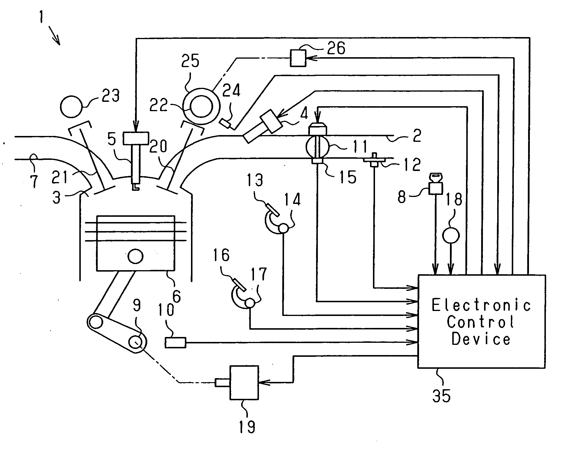
[0018] A preferred embodiment will now be described with reference to FIGS. 1 to 5. In this embodiment, the present invention is applied to an automobile engine that is automatically stopped and restarted.

[0019] In an engine 1 shown in FIG. 1, based on depression of an accelerator pedal 13, the opening degree of a throttle valve 11 provided in an intake passage 2 is adjusted to control the amount of air drawn into combustion chambers 3 (only one is shown) from the intake passage 2. The engine 1 has fuel injection valves 4 each corresponding to one of the combustion chambers 3. Each fuel injection valve 4 injects fuel the amount of which corresponds to the amount of air drawn into the associated combustion chamber 3. The air-fuel mixture is ignited in each combustion chamber 3 by an ignition plug 5. The ignition burns the air-fuel mixture and produces combustion energy. The combustion energy reciprocates a piston 6. Accordingly, a crankshaft 9, which is an output shaft of the engine...


PUM


Abstract

A control apparatus includes a driving device that is capable of operating regardless whether the engine is running or not. A variable valve actuation mechanism is driven by the driving device. During an idling operation of the engine, a control section controls the driving device such that the variable valve actuation mechanism maintains the valve timing at a valve timing advanced relative to a most retarded valve timing. The control section controls the driving device such that the variable valve actuation mechanism changes the valve timing to the most retarded valve timing after a stopping operation of an autonomous operation of the engine is initiated. Therefore, shock due to the initiation of the engine starting operation is reduced without decreasing fuel economy.

Description

BACKGROUND OF THE INVENTION [0001] The present invention relates to a valve timing control apparatus and method for internal combustion engines. [0002] To optimize the power and fuel economy throughout the entire engine operating range, internal combustion engines, such as automobile engines, that are equipped with a variable valve actuation mechanism for changing the valve timing of intake valves according to the engine operating state have been made practical. For example, variable valve actuation mechanisms are known that are provided with oil from a mechanical oil pump and operate based on the pressure of the oil. [0003] To perform stable combustion while guaranteeing necessary compression ratio during an idling operation of such an internal combustion engine, the valve timing of intake valves is set to timing that guarantees the necessary compression ratio (hereinafter, referred to as idling valve timing). [0004] Also, when an engine starting operation is initiated (when cranki...

Claims


Application Information

Patent Timeline
Patent Type & Authority Applications(United States)
IPC IPC(8): F02N17/00F02M1/00F01L1/34F02N99/00F01L13/00F02D13/02F02D15/00F02D29/02F02D41/06
CPCF01L1/0532F01L1/344F01L1/352F01L9/04F01L2001/0537F01L2009/0411F01L2800/01F01L2800/03F01L2820/032F01L2820/041F02D13/0238F02D13/08F02D41/042F02N11/0814F02N19/004Y02T10/18F01L9/20F01L9/22Y02T10/12
Inventor MASHIKI, ZENICHIRO
Owner TOYOTA JIDOSHA KK
Why Eureka
Try Eureka