Industrial two-layer fabric

a fabric and two-layer technology, applied in the field of industrial fabric, can solve the problems of poor water drainage property and air permeability, difficulty in increasing the number of wefts, and forming a dense surface, and achieve the effects of improving surface properties, fiber support properties, and rigidity

Active Publication Date: 2006-05-18
NIPPON FILCON
View PDF23 Cites 18 Cited by
  • Summary
  • Abstract
  • Description
  • Claims
  • Application Information

AI Technical Summary

Benefits of technology

[0009] The industrial two-layer fabric according to the present invention comprises pairs of an upper surface side warp and a lower surface side warp arranged vertically, and warp binding yarns woven with upper surface side wefts and lower surface side wefts form a portion of an upper surface side surface design

Problems solved by technology

This fabric is however accompanied with such a drawback that owing to an increase in the number of knuckles, it is difficult to increase the count of wefts and form a dense surface.
In a

Method used


Image

  • Industrial two-layer fabric
  • Industrial two-layer fabric
  • Industrial two-layer fabric

Examples


example 1

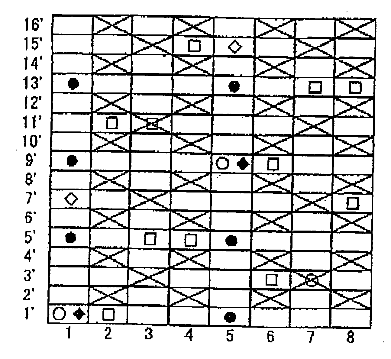
[0048] In the design diagram of FIG. 1, indicated at numerals 2, 3, 4, 6, 7 and 8 are pairs of an upper surface side warp and a lower surface side warp arranged vertically, while indicated at numerals 1 and 5 are pairs of warp binding yarns. Indicated at 1′, 2′, and 3′ to 16′ are wefts and an upper surface side weft and a lower surface side weft are arranged vertically. Upper surface side wefts and lower surface side wefts are arranged at 2:1 and they are arranged vertically with the lower surface side wefts being laid under odd-numbered upper surface side wefts.

[0049] As is apparent from the cross-sectional views of FIGS. 13A and 13B taken along warps 1 and 2, the fabric of Example 1 is a 16-shaft two-layer fabric obtained by alternately arranging, on the upper surface side surface of the fabric, a warp complete design obtained by repeating a design in which a warp passes over one upper surface side weft and then passes under one upper surface side weft and another warp complete d...

example 2

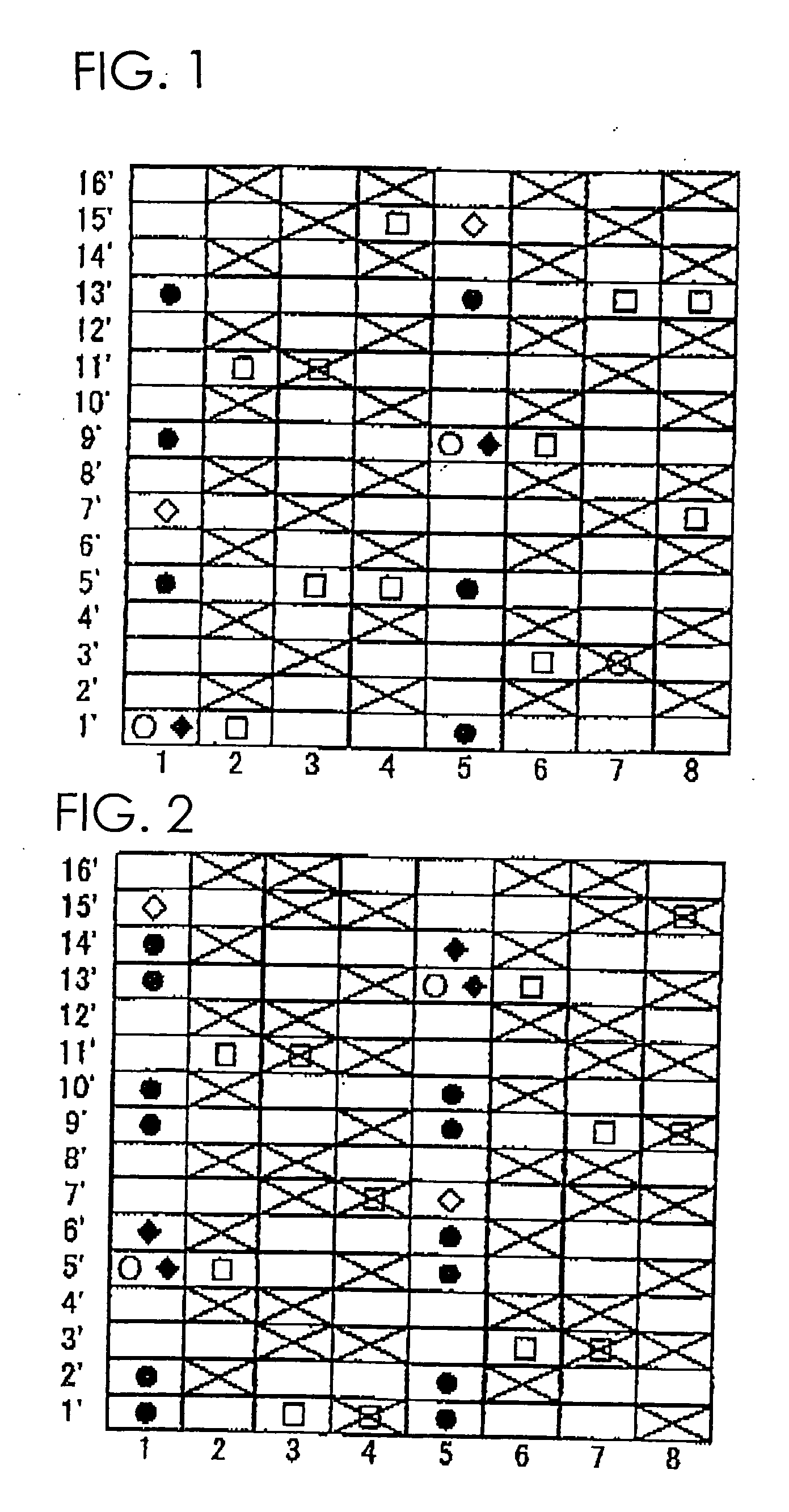
[0056] Another example of the fabric according to the present invention is shown in FIG. 2. This fabric is a 16-shaft two-layer fabric having, on the upper surface side surface thereof, alternately arranged two warp complete designs, that is, a warp complete design obtained by repeating a design in which a warp passes over one upper surface side weft and then passes under one upper surface side weft and a warp complete design obtained by repeating a design in which a warp passes over two upper surface side wefts and then passes under two upper surface side wefts. Pairs of warp binding yarns and pair of an upper surface side warp and a lower surface side warp are arranged at a ratio of 1:3. The pairs of warp binding yarns form, on the upper surface side surface, a warp complete design obtained by repeating a design in which it passes over two upper surface side wefts and then passes under two upper surface side wefts.

[0057] This example is different from Example 1 in a warp complete...

example 3

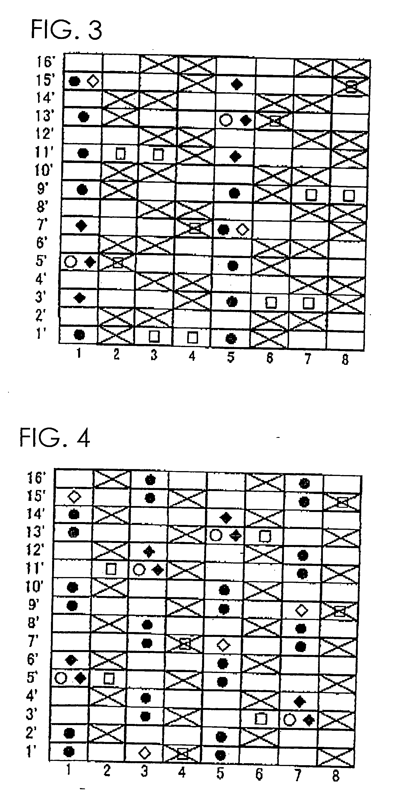
[0059] A further example of the fabric according to the present invention is illustrated in FIG. 3. The fabric of this example has a similar upper surface side surface design to that of Example 2 except that pairs of warp binding yarn have, on the upper surface side surface, a warp complete design obtained by repeating a design in which a warp binding yarn passes over one upper surface side weft and then passes under one upper surface side weft. Even by this example, a fabric excellent in surface property, fiber supporting property, rigidity, air permeability and water drainage property and having an upper surface side surface densified by an increase in the count can be obtained.


PUM


Abstract

An industrial two-layer fabric obtained by alternately arranging, on an upper surface side thereof, (a) a warp complete design made of a design in which a warp passes over one upper surface side weft and then passes under one upper surface side weft, and any one of the following warp complete designs of: (b) a warp complete design made of a design in which a warp passes over two upper surface side wefts and then passes under two upper surface side wefts, (c) a warp complete design made of a design in which a warp passes over one upper surface side weft and then passes under three upper surface side wefts, (d) a warp complete design made of a design in which a warp passes over three upper surface side wefts and then passes under one upper surface side weft, and others.

Description

TECHNICAL FIELD [0001] The present invention relates to an industrial fabric comprising warp binding yarns and capable of satisfying all the requirements necessary for industrial fabrics such as surface property, fiber supporting property, rigidity, running stability and water drainage property. BACKGROUND OF THE INVENTION [0002] Fabrics obtained by weaving warps and wefts have conventionally been used widely as an industrial fabric. They are, for example, used in various fields including papermaking wires, conveyor belts and filter cloths and are required to have fabric properties suited for the intended use or using environment. Of such fabrics, a papermaking wire used in a papermaking step for removing water from raw materials by making use of the network of the fabric must satisfy a severe demand. There is therefore a demand for the development of fabrics which do not transfer a wire mark of the fabric and therefore have excellent surface property, have enough rigidity and there...

Claims


Application Information

Patent Timeline
IPC IPC(8): D21F1/00
CPCD21F1/0036
Inventor UEDA, IKUONAGURA, HIROYUKI
Owner NIPPON FILCON
Why Eureka
Try Eureka