Thermal - acoustic enclosure

a technology of enclosures and enclosures, applied in the field of enclosures for equipment, can solve the problems of increased excessive weight of the enclosure, and excessive weight of the engine enclosure, and achieve the effect of increasing the fuel consumption of the vessel, increasing the sound attenuation or transmission loss, and increasing the weight of the enclosur

Active Publication Date: 2006-05-18
GENERAL ELECTRIC CO
View PDF12 Cites 18 Cited by
  • Summary
  • Abstract
  • Description
  • Claims
  • Application Information

AI Technical Summary

Problems solved by technology

Typically, current designs of such enclosures include heavy metal structures based on the theory that mass is the primary factor in sound attenuation and therefore increased mass results in increased sound a

Method used


Image

  • Thermal - acoustic enclosure
  • Thermal - acoustic enclosure
  • Thermal - acoustic enclosure

Examples


Embodiment Construction

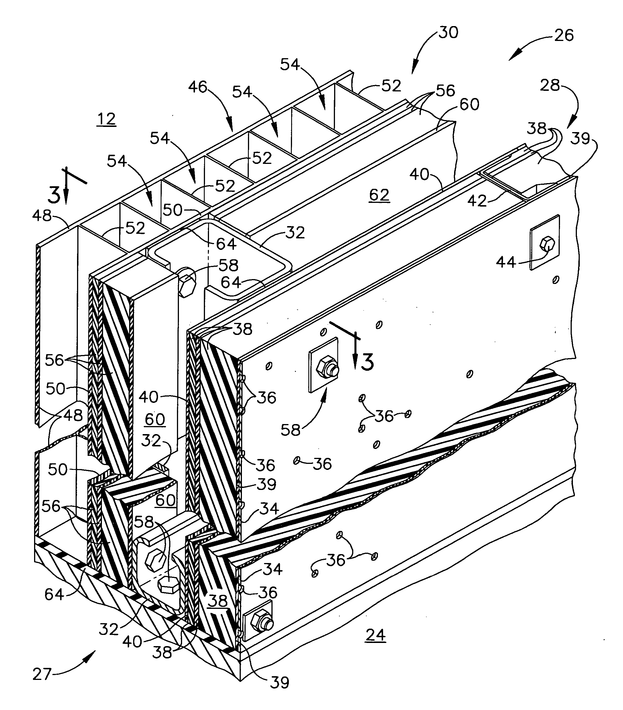
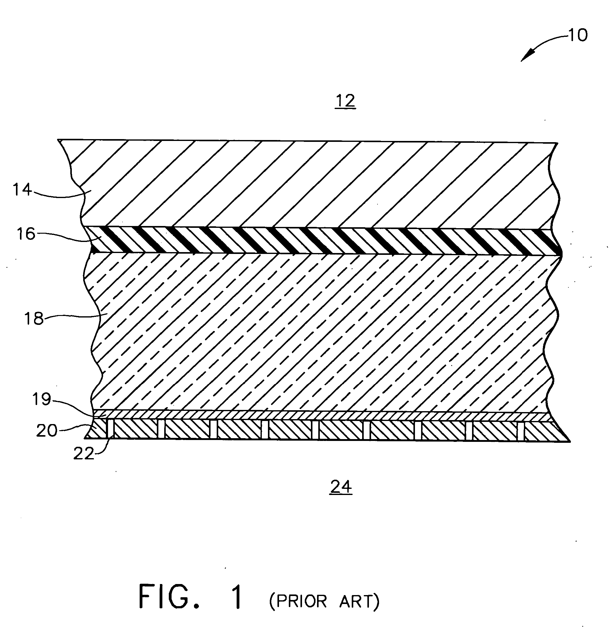
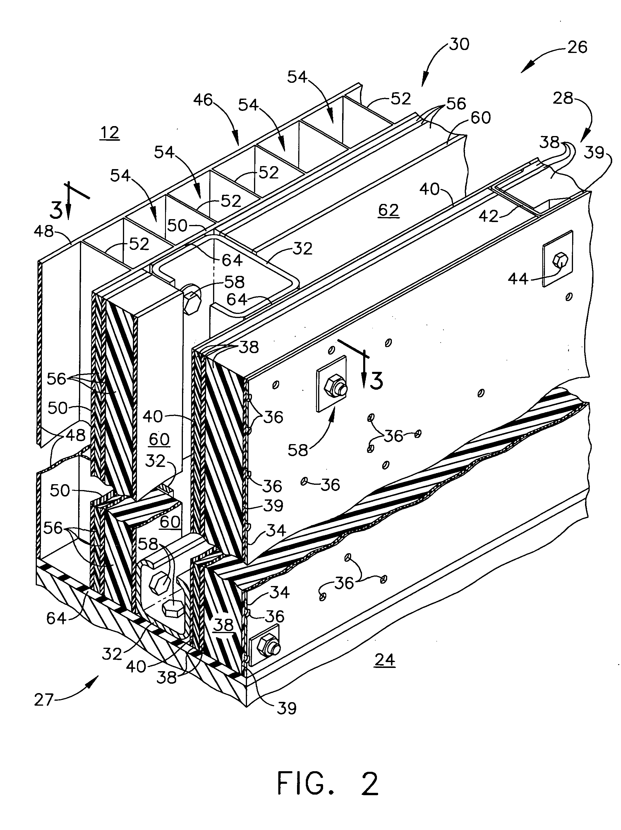
[0017] Current enclosure designs used to package or house gas turbine engines for use in marine applications provide acoustic transmission loss requirements with heavy metal structures. One form of a wall of such current, prior art enclosures is shown generally at 10 in the diagrammatic, fragmentary sectional view of FIG. 1. Wall 10 comprises, in sequence from outside 12 of enclosure wall 10, a heavy metal plate 14, a sprayed-on thick rubber coating material 16, felt batting material 18 (typically including a thin film facing 19) to provide damping of acoustic energy, and a perforated metal face sheet 20 (including pores 22 therethrough) adjacent enclosure inside or enclosure hollow interior 24. Supporting such prior art structure is a large number of heavy metal stiffening beams (not shown). Such current design results in an extremely heavy structure for an enclosure in order to satisfy specified sound energy attenuation requirements.

[0018] Forms of the present invention eliminate...


PUM


Abstract

An enclosure for apparatus that, during operation, generates heat and/or sound energy comprises at least one wall defining at least a portion of the enclosure hollow interior. The wall comprises in sequence outwardly from the enclosure hollow interior an inner panel, an outer panel, a support frame between the inner and outer panels to hold the inner and outer panels spaced apart, and a vibrator isolator between the support frame and the panels. Panels or panel segments of the wall primarily are made of non-metallic composites to provide a structurally strong, lightweight enclosure that includes enhanced acoustic characteristics and reduced heat transfer through enclosure walls, along with fire protection and in-plane shear loading capabilities.

Description

BACKGROUND OF THE INVENTION [0001] This invention relates to enclosures for apparatus that, during operation, generates heat and sound energy. More particularly, it relates to an enclosure for a turbine engine used for such applications as marine or industrial. [0002] Gas turbine engines used to generate power in marine or industrial applications are required to be contained or packaged in an enclosure to reduce levels of noise or sound energy and heat generated during engine operation, as well as to provide fire protection. Typically, current designs of such enclosures include heavy metal structures based on the theory that mass is the primary factor in sound attenuation and therefore increased mass results in increased sound attenuation or transmission loss. Accordingly, the walls of current enclosures include heavy, solid and porous metal plates with a large number of stiffening beams to achieve a desired sound frequency attenuation. Damping compound is added to provide damping o...

Claims


Application Information

Patent Timeline
IPC IPC(8): G10K11/04E04B1/82E04B2/02E04B1/00E04B9/00
CPCE04B1/8218E04B2001/748E04B2001/8461F23M20/005F02K1/827F05D2260/96F02C7/24
Inventor MITCHELL, STEPHEN CRAIGBENSON, JAY ALANROYAL, GLEN WILLIAM
Owner GENERAL ELECTRIC CO
Why Eureka
Try Eureka