

Friction plate for wet-type multiplate clutch
a multi-plate clutch and friction plate technology, applied in the direction of fluid-actuated clutches, clutches, non-mechanical actuated clutches, etc., can solve the problems of shifting shock, increase in idling drag, and reduce the force, so as to reduce the drag upon idling and stable friction characteristics
- Summary
- Abstract
- Description
- Claims
- Application Information
AI Technical Summary
Benefits of technology
Problems solved by technology
Method used
Image

Examples
Embodiment Construction
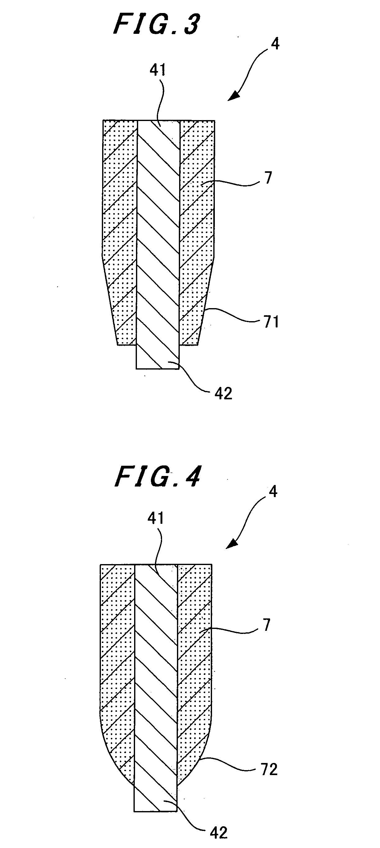
[0020] In the present invention, the friction linings on each friction plate are each formed such that at a section thereof located on a side radially inner than a radial center line thereof, the friction lining has a thickness that gradually increases from an inner circumferential portion of the section toward an outer circumferential portion of the section. Each of the friction linings can define a planar, curved or stepped surface at the section. Further, the section and a remaining section of each friction lining can be made of materials having different compression characteristics, respectively.
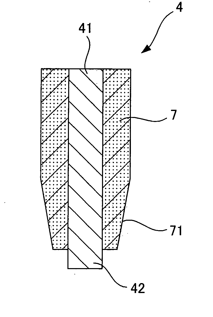
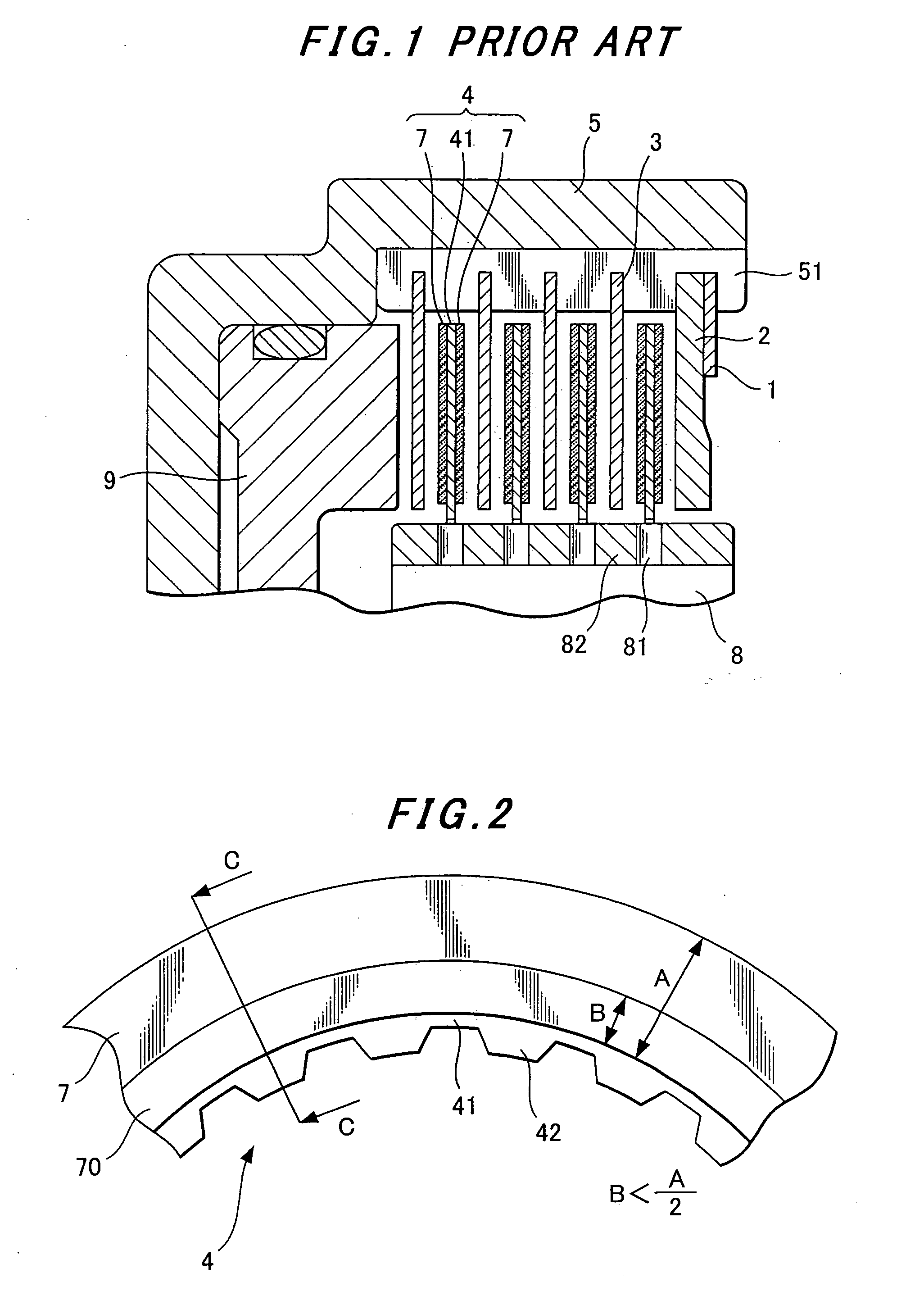
[0021] Referring first to FIG. 2, a friction lining 7 fixed on a core plate 41 of a friction plate 4 (see FIG. 1), the entire radial width of said friction lining being indicated by letter A, is formed such that at an annular section 70 located on a side radially inner than a radial center line of the friction lining 7, the friction lining 7 has a thickness that gradually increases from...
PUM
 Abstract
Description
Claims
Application Information