
Vacuum high-temperature friction-wear tester

A friction and wear test, high temperature technology, used in instruments, scientific instruments, testing wear resistance, etc., can solve problems such as equipment cannot be used normally, actual operation is inconvenient, and force measurement results are inaccurate.

Pending Publication Date: 2020-07-07
兰州华汇仪器科技有限公司
View PDF10 Cites 4 Cited by
  • Summary
  • Abstract
  • Description
  • Claims
  • Application Information

AI Technical Summary

Problems solved by technology

[0003] One is that the structure of a high-temperature vacuum friction and wear testing machine has changed greatly from the existing friction and wear testing machine and high-temperature friction and wear testing machine, which is not conducive to the integrated use of equipment. Multiple equipment is required to perform different tests, and the actual operation is extremely inconvenient , resulting in a serious waste of resources;
[0004] The second is that a high-temperature vacuum friction and wear testing machine does not have a good heat dissipation function, which may easily cause excessive heating and excessive residual temperature transmission, resulting in the overall high temperature of the equipment, causing the equipment to not work normally and the experimental data to be inaccurate;
[0005] The third is to add a vacuum system to the high-temperature friction and wear testing machine to realize the function of vacuum high-temperature friction and wear testing. , when the force measurement results are inaccurate

Method used


Image

  • Vacuum high-temperature friction-wear tester
  • Vacuum high-temperature friction-wear tester
  • Vacuum high-temperature friction-wear tester

Examples


Embodiment Construction

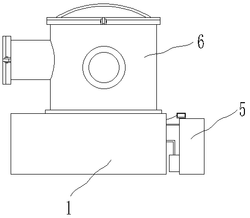
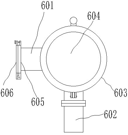
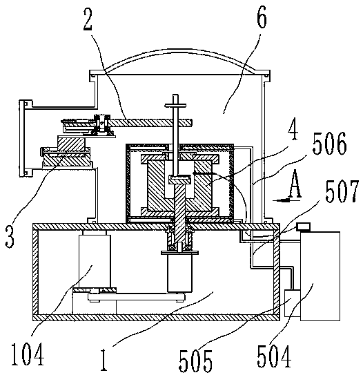
[0035]The present invention will be described in detail below in conjunction with the accompanying drawings and specific embodiments: a vacuum high-temperature friction and wear tester, characterized in that it includes a machine base 1, a force-measuring assembly 2, an adjustment bracket 3, a heating furnace assembly 4, and a cooling circulation system 5 and a vacuum cover 6, the vacuum cover 6 is arranged above the machine base 1, the force measuring assembly 2, the adjustment bracket 3, the heating furnace assembly 4 and the cooling circulation system 5 are arranged in the vacuum cover 6, and the cooling circulation system 5 is connected to the machine Above the seat 1, the heating furnace assembly 4 is arranged in the cooling circulation system 5, the left end of the vacuum cover 6 is provided with a supporting connecting pipe 601, the adjusting bracket 3 is connected in the supporting connecting pipe 601, the left end of the force measuring assembly 2 is connected on the ad...


PUM


Abstract

The invention relates to material surface performance test equipment, and particularly relates to a vacuum high-temperature friction-wear tester. The tester is characterized in that a vacuum cover isarranged above a machine base, a force measuring assembly, an adjusting support, a heating furnace assembly and a cooling circulation system are arranged in the vacuum cover, the cooling circulation system is connected above the machine base, the heating furnace assembly is arranged in the cooling circulation system, a supporting connecting pipe is arranged at the left end of the vacuum cover, theadjusting support is connected in the supporting connecting pipe, the left end of the force measuring assembly is connected to the adjusting support, the right end of the force measuring assembly isconnected with a loading rod, the loading rod penetrates through the force measuring assembly, the heating furnace assembly comprises a furnace body, a heating cavity is formed in the furnace body, the loading rod is inserted into the heating cavity, a friction disc is arranged in the heating cavity, a detection piece is clamped between the loading rod and the friction disc, the lower end of the friction disc is connected with a rotating shaft, the rotating shaft penetrates through the heating furnace assembly and the cooling circulation system, the lower end of the rotating shaft is rotationally connected into the machine base, and the side wall of the vacuum cover is further connected with a molecular pump unit.

Description

technical field [0001] The invention relates to material surface performance test equipment, in particular to a vacuum high-temperature friction and wear tester. Background technique [0002] Vacuum high-temperature friction and wear tester is an instrument for material surface performance testing, which is widely used in the field of material science and technology. Chinese patent 201710120263.X discloses a high-temperature vacuum friction and wear tester, and Chinese patent 201310311447.6 discloses a The high temperature friction and wear testing machine has the following problems in combination with the characteristics of the two testing machines: [0003] One is that the structure of a high-temperature vacuum friction and wear testing machine has changed greatly from the existing friction and wear testing machine and high-temperature friction and wear testing machine, which is not conducive to the integrated use of equipment. Multiple equipment is required to perform dif...

Claims


Application Information

Patent Timeline
IPC IPC(8): G01N3/56G01N3/02
CPCG01N3/56G01N3/02G01N2203/0226G01N2203/0228G01N2203/0676
Inventor 华敏奇张国珍
Owner 兰州华汇仪器科技有限公司
Learn More