Separator plate for wet-type multiplate clutch and wet-type multiplate clutch provided with such separator plates

a separator plate and multi-plate technology, which is applied in the direction of mechanical actuated clutches, manufacturing tools, mechanical equipment, etc., can solve the problems of unavoidable accompanation of wet-type multi-plate clutches using such conventional separator plates, large variation in friction characteristics, coefficient of friction, etc., to prevent wear of frictional materials, facilitate and efficiently manufacture, and maintain frictional characteristics for an extended period

Active Publication Date: 2006-08-29
NSK WARNER
View PDF8 Cites 5 Cited by
  • Summary
  • Abstract
  • Description
  • Claims
  • Application Information

AI Technical Summary

Benefits of technology

[0010]The separator plate according to the present invention and the wet-type multiplate clutch according to the present invention, said wet-type multiplate clutch being provided with such separator plates, can maintain friction characteristics stable over an extended period, and can also prevent wearing of frictional materials as counterpart members. The manufacturing method according to the present invention can readily and efficiently manufacture the above-described separator plate.

Problems solved by technology

A wet-type multiplate clutch making use of such conventional separator plates is unavoidably accompanied by an inconvenience that its friction characteristics vary considerably depending on the oil temperature.
Especially when the oil temperature is low and the engagement load is also low, a problem arises in that, as will be mentioned subsequently herein, oil films are formed between the separator plates and their associated friction plates to extremely lower the coefficient of friction.
The above-described conventional separator plate is, however, still accompanied by the drawback that the peak portions of the lands, said peak portions being to project toward a friction material as its counterpart member when the separator plate is assembled in a wet-type multiplate clutch, unavoidably causes the friction material to wear out, although the peak portions of the lands with oil grooves formed therebetween have been rounded.

Method used


Image

  • Separator plate for wet-type multiplate clutch and wet-type multiplate clutch provided with such separator plates
  • Separator plate for wet-type multiplate clutch and wet-type multiplate clutch provided with such separator plates
  • Separator plate for wet-type multiplate clutch and wet-type multiplate clutch provided with such separator plates

Examples


examples

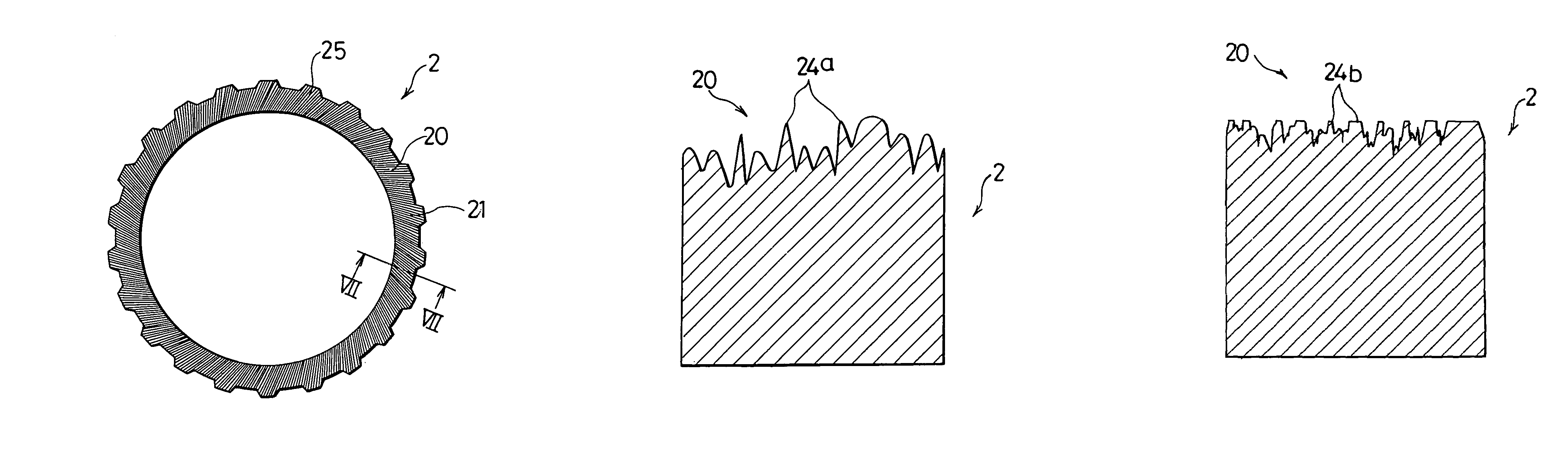
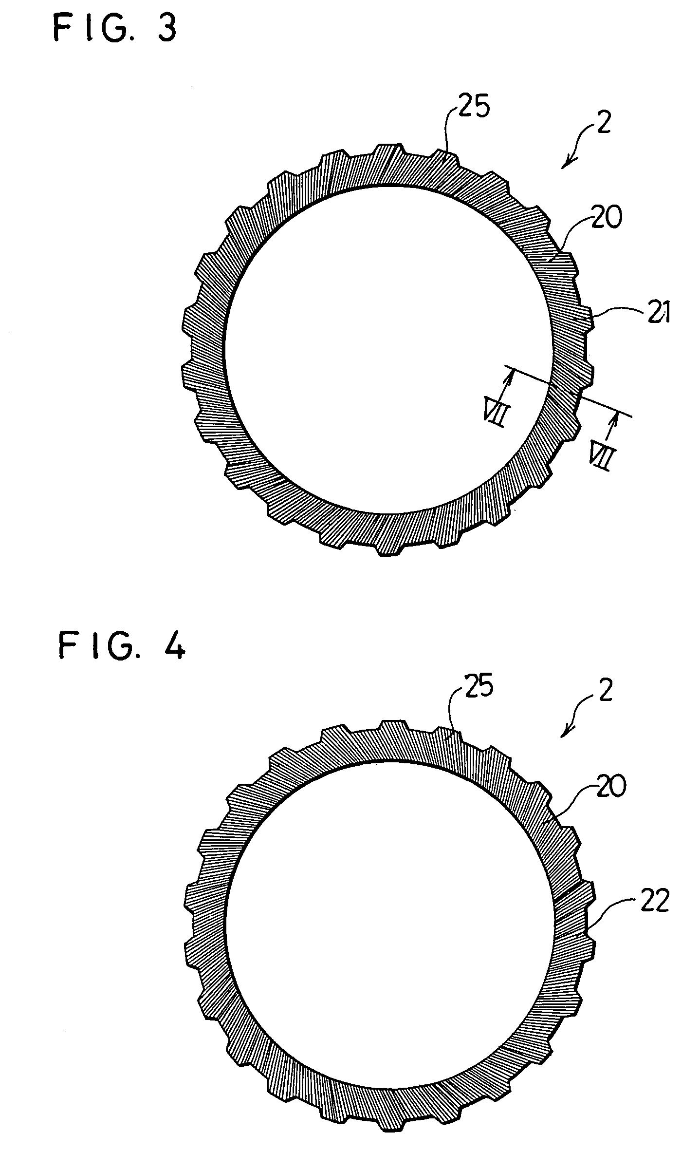
[0023]FIG. 3 illustrates the separator plate 2 according to the first embodiment of the present invention. Elongated asperities 21 are formed on a friction surface 20 such that the elongated asperities 21 are tilted in a clockwise direction. FIG. 4 depicts the separator plate 2 according to the second embodiment of the present invention. Elongated asperities 22 are formed on a friction surface 20 such that the elongated asperities 21 are tilted in a couterclockwise direction. Further, FIG. 5 shows the separator plate 2 according to the third embodiment of the present invention. The separator plate 2 according to the third embodiment is provided on a friction surface 20 thereof with asperities 23 formed in a crosshatch pattern. These asperities 23 can be formed by cutting valleys on the friction surface 20 at predetermined intervals and at a predetermined angle, for example, 90° with respect to the inclined angle of the elongated asperities 21 or 22. In each of FIGS. 3 through 5, num...


PUM

PropertyMeasurementUnit
heightsaaaaaaaaaa
inclined angleaaaaaaaaaa
plateau heightaaaaaaaaaa

Abstract

A separator plate useful in a wet-type multiplate clutch is provided on a friction surface thereof with elongated asperities extending with regularity in a predetermined direction. Peak portions of the elongated asperities, said peak portions being to project toward a counterpart member when the separator plate is assembled in the wet-type multiplate clutch, have been removed to form elongated plateaus. The separator plate can be manufactured by fixedly mounting a blank for the separator plate on a work support, forming elongated asperities with regularity in a predetermined direction on one of opposite surfaces of the blank by a grinding wheel, and then removing peak portions of the elongated asperities, said peak portions being to project toward a counterpart member when the separator plate is assembled in the wet-type multiplate clutch, to form elongated plateaus.

Description

FIELD OF THE INVENTION[0001]This invention relates to a separator plate for a wet-type multiplate clutch useful in an automatic transmission, and also to a wet-type multiplate clutch provided with such separator plates. The present invention is also concerned with a method for manufacturing such a separator plate.DESCRIPTION OF THE BACKGROUND[0002]FIG. 1 is a side cross-sectional view showing the basic construction of a wet-type multiplate clutch 10. The drawing shows a clutch case 1, separator plates 2, friction plates 3, and a piston 4 for pressing the separator plates 2 and friction plates 3 toward a stopper ring 5. When pressure oil is introduced into an oil compartment 41 through an oil hole 44, the piston 4 is pressed rightwards as viewed in the drawing. When the pressure oil is drawn, on the other hand, the piston 4 is returned leftwards by a return spring 43 arranged between a piston support 42 and the piston 4. At this time, pressure oil is allowed to enter the oil compartm...

Claims


Application Information

Patent Timeline
Patent Type & Authority Patents(United States)
IPC IPC(8): B23P25/00B23P17/00B24B1/00F16B13/00F16D13/62F16D13/64F16D25/0638
CPCF16D13/648F16D25/0638Y10T29/49229Y10T29/49977Y10T29/49975Y10T29/49995
Inventor KINPARA, HIROYUKISAKABE, MASAKI
Owner NSK WARNER
Why Eureka
Try Eureka