Cross-connection method for steel pipe and H-shape steel

A cross-connection, H-beam technology, applied in joists, girders, trusses, etc., can solve the problems of unstable quality, high cost, difficult on-site construction, etc., and achieve the effect of reducing quality accidents, reducing usage, and avoiding fires

Inactive Publication Date: 2005-07-20
佐藤 孝典
View PDF1 Cites 4 Cited by
  • Summary
  • Abstract
  • Description
  • Claims
  • Application Information

AI Technical Summary

Problems solved by technology

[0005] The purpose of the present invention is to provide a new method for connecting steel pipes and H-shaped steels in view of the actual problems exis

Method used


Image

  • Cross-connection method for steel pipe and H-shape steel
  • Cross-connection method for steel pipe and H-shape steel
  • Cross-connection method for steel pipe and H-shape steel

Examples


Embodiment 1

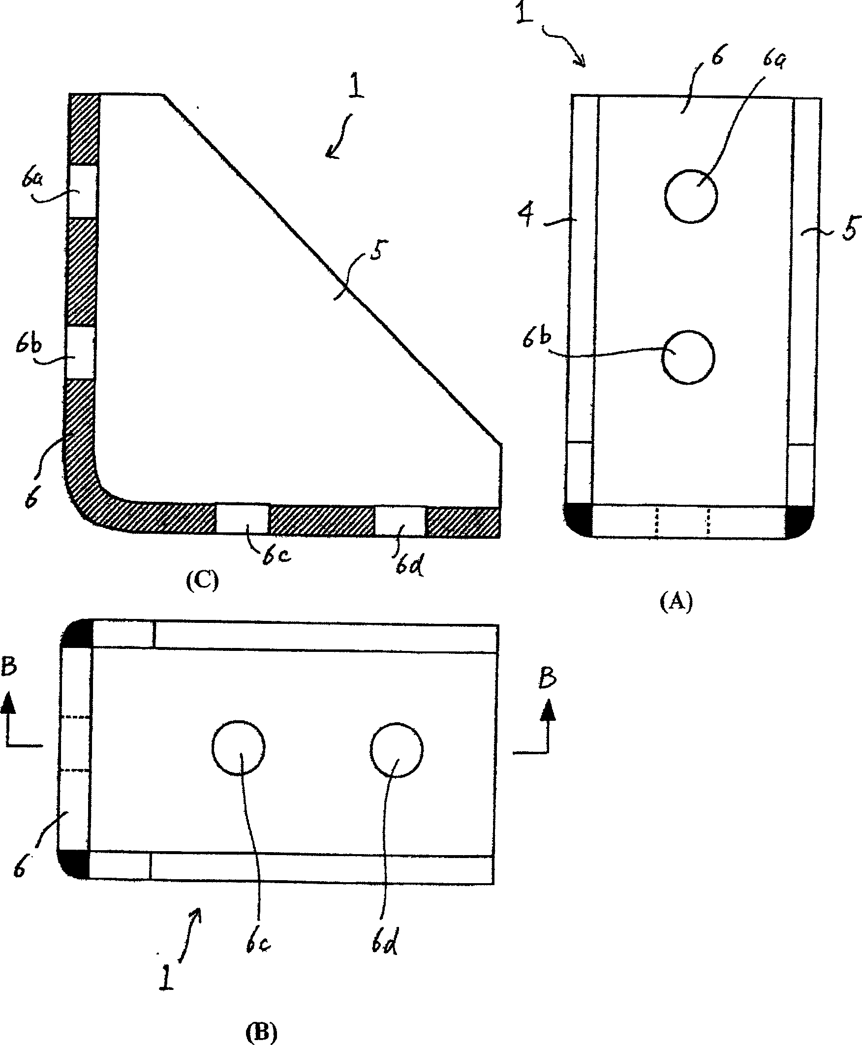
[0044] The angle steel 1 that uses among the embodiment 1 also can be as figure 2 As shown in , the bottom plate and the vertical plate are bent from one member to form an angle steel 6 with a part of the curved surface on the outside, and then the ribs 4 and 5 as side plates are welded to it, and there are also bolt through holes 6a -6d, in this way, it can also cope with the case where the joint part has an arc.

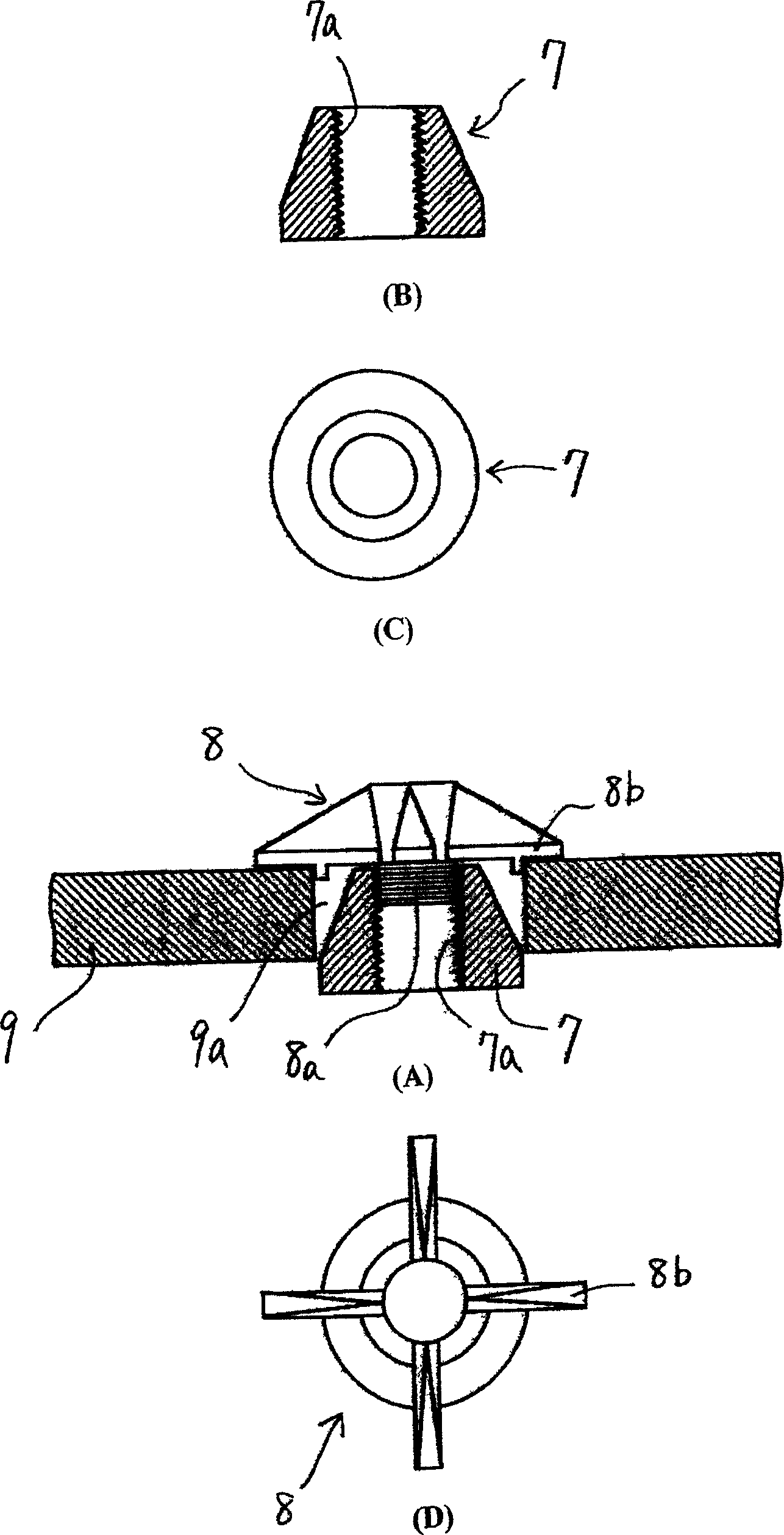
[0045] image 3 and Figure 4 It is an explanation about forming internal threads on the pipe wall of a pile or column. Such as image 3 As shown, at the hole 9a for forming the internal thread of the angled steel pipe 9 placed horizontally, the nut 7 shown in (B) and (C) of the structure is first temporarily connected with the temporary fixing member 8, and the temporary fixing is used. The component 8 is provided with a screw rod 8a and a fixed rod 8b. The top view of the temporarily connected assembly is shown in (D) in the figure. The temporarily connected ...

Embodiment 3

[0050] Figure 11 discloses Embodiment 3 of the present invention. In this embodiment, an elongated bolt hole 10b is opened on the H-shaped steel 10 so that the friction surface can slide. The rubber plate 14 wrapped tightly by the steel pipe, and finally the nut is tightened from the outermost side. All the pulling force of the bolt acts on the rubber plate. Rubber sheet wrapped tightly with steel pipe 14 such as Figure 12 As shown, the cylindrical rubber 14a is embedded in the steel pipe 14b to form a whole. Figure 13 The rubber sheet 14 shown in (A)-(D) is an example of multilayer rubber. By adopting the above scheme, the effect of absorbing vibration energy can be realized.

[0051] Figure 14 Embodiment 4 related to the present invention is disclosed. In this embodiment, the nuts 7 are not welded on the openings of the steel pipe 9 one by one, but as Figure 14 As shown in (A), screw holes 15a are formed on one plate to form a nut plate 15. The temporary fixing mem...


PUM


Abstract

The invention relates to a cross-linking method for connecting a steel pipe with an H-type steel. The invention is to drill holes on the pipe wall of the steel pipe at the cross-contact where the steel pipe connects with the H-type steel of steel building, to arrange internal threads in the hole or to outstretch bolts from the holes which pass through angle steels strengthened by ribbed slabs, and to fix H-type steel onto the outside of the steel pipe. The invention has the advantages that welding operations in construction site are avoided and welding defects, quality accidents caused by welding and fire disaster caused by welding sparks are all reduced because internal threads are preformed on the wall of the steel, ribbed slabs are arranged on the two side of the angle steel so that the angle steel can transmit shearing force, the web plate of the H-type steel needs not to connect with the steel, angle steel can resists horizontal pull and stress greater force in vertical direction compared with the current L-type angle steel, and the usage amount of the bolts and the cost can be reduced after a board used for increasing friction coefficient is inserted between the steels mutually connected.

Description

technical field [0001] The invention relates to a method for cross-connecting steel pipes and H-shaped steels at the column-beam junctions and support parts of a steel structure building. technical background [0002] In the connection of steel pipes and H-beams, since the inside of the steel pipes cannot be operated, welding is generally the main method, but the reliability of welding is affected by the proficiency of welders, and the lack of skilled welders may lead to unstable welding quality. [0003] In addition, due to the relatively small friction coefficient between the steel plates, the number of bolts will increase, the size of the connecting components will increase, and the cost will increase. In addition, there are also cases where T-shaped members are used for this kind of cross-combined connection. In this case, although the tensile stiffness is relatively large, because the joint adopts single-sided friction, the number of bolts required is large, which is re...

Claims


Application Information

Patent Timeline
IPC IPC(8): E04B1/24E04B1/58E04C3/04E04C3/32
Inventor 佐藤孝典
Owner 佐藤 孝典
Why Eureka
Try Eureka