Cleaning unit and image forming apparatus

a technology of cleaning unit and image forming apparatus, which is applied in the direction of vehicle cleaning, manufacturing tools, instruments, etc., can solve the problems of increasing load torque, increasing contact pressure applied from the blade, and increasing frictional force in the contact region, so as to achieve the effect of stabilizing the frictional for

Inactive Publication Date: 2014-06-10
CANON KK
View PDF10 Cites 5 Cited by
  • Summary
  • Abstract
  • Description
  • Claims
  • Application Information

AI Technical Summary

Benefits of technology

[0009]A principal object of the present invention is to provide a cleaning unit and an image forming apparatus which are capable of stabilizing a frictional force between a blade (cleaning member) and a member-to-be-cleaned even when an “apparent friction coefficient” is fluctuated by a change with time or a change in operation environment.

Problems solved by technology

In the counterdirectional contact type in which the cleaning performance is improved, a rise in contact pressure applied from the blade onto the member-to-be-cleaned and a rise in frictional force in a contact region are caused simultaneously.
As a result, problems can arise such as a rise in load torque of a motor for driving the member-to-be-cleaned, abrasion (wearing) of the member-to-be-cleaned, an unusual noise due to vibration of the blade generated in the contact region, and worsening of the cleaning performance.
Or, there can arise problems such as stop, breakage and the like of the device due to turning up of the blade at a contact portion between the blade and the member-to-be-cleaned and warp around of the blade toward a downstream direction of the member-to-be-cleaned.
In the case where the toner of small in particle size and high in circularity contacts the member-to-be-cleaned, there is a tendency that it is difficult to collect the toner by the blade.
An increase in surface urging force by the member-to-be-cleaned leads to further increase in frictional force between surfaces of the blade and the member-to-be-cleaned, thus resulting in a state in which turning-up and shuddering of the blade, the abrasion of a surface layer of the member-to-be-cleaned, and the like are liable to occur more than ever before.
However, in the constitution described in JP-A 2007-114392, in the case where an “apparent friction coefficient” between the cleaning member and a secondary transfer roller is increased, there is a possibility that the frictional force is increased.

Method used


Image

  • Cleaning unit and image forming apparatus
  • Cleaning unit and image forming apparatus
  • Cleaning unit and image forming apparatus

Examples


embodiment 2

(Embodiment 2)

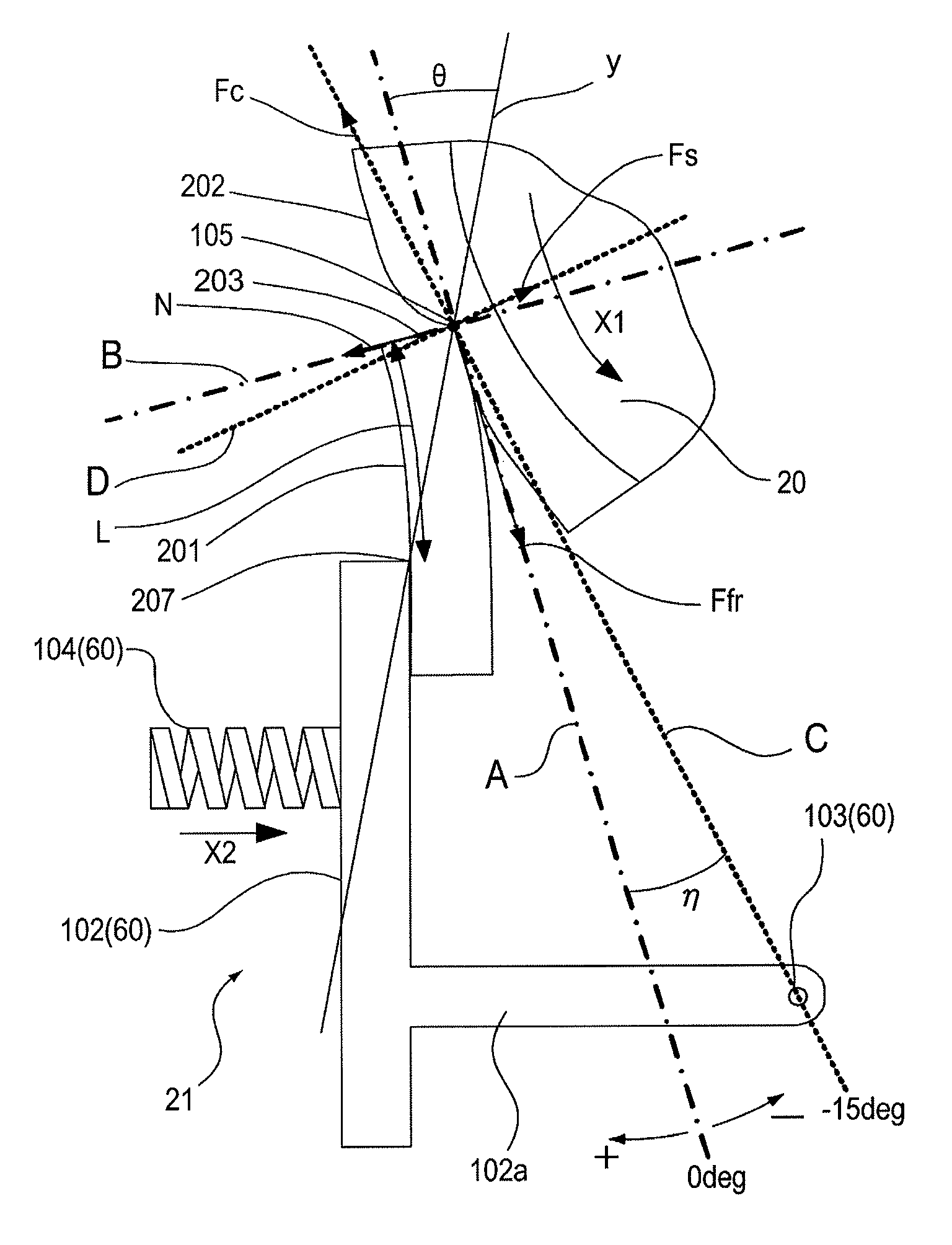
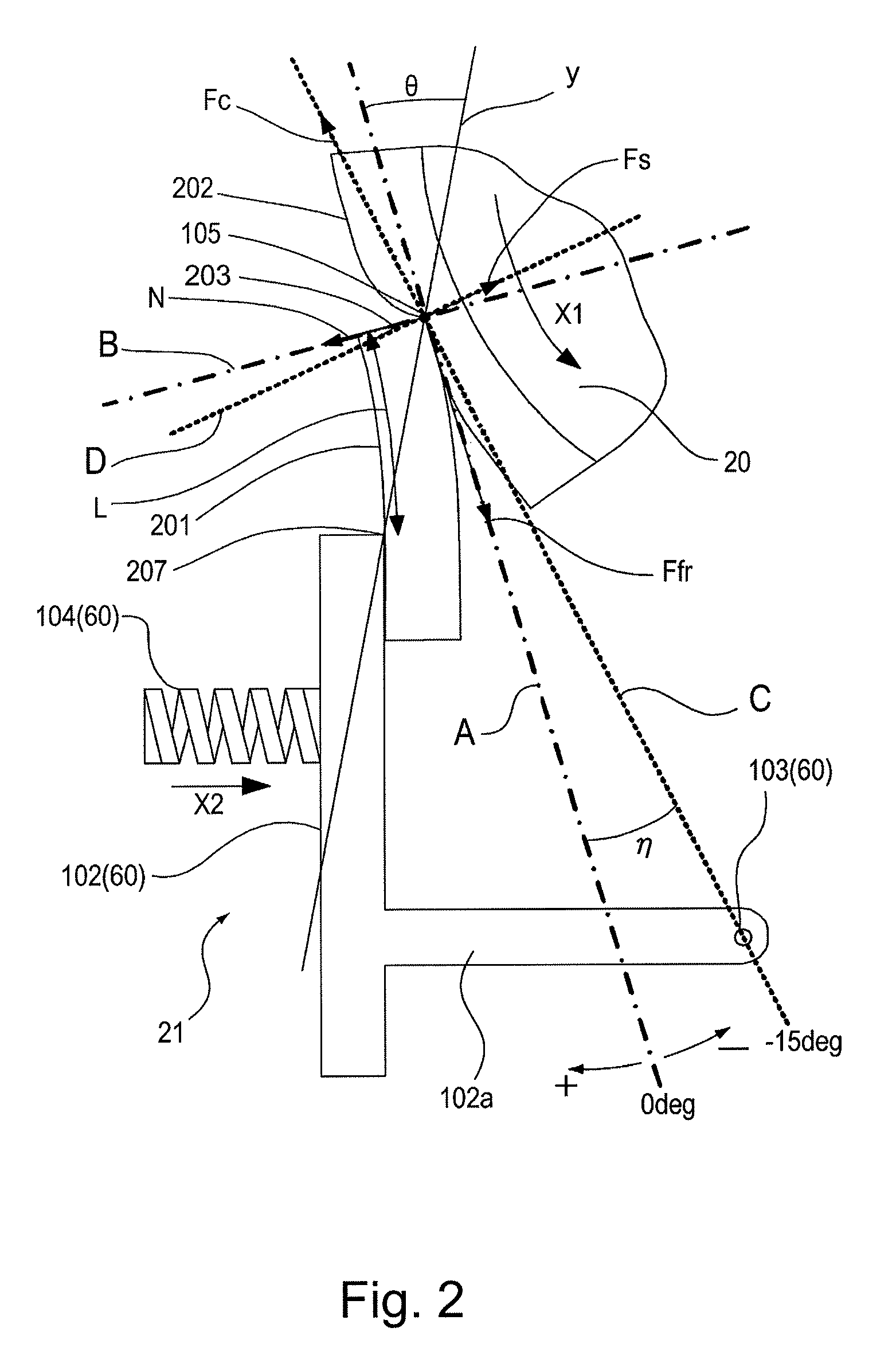
[0089]A constitution of a cleaning unit 221 in Embodiment 2 is shown in (a) of FIG. 7. In Embodiment 2, the constitution in which the position of the swing center point 103 is changed is compared with those in Comparative Embodiments, so that the reason that the functional effect of this embodiment is obtained and the scope of the present invention regarding the swing center position angle η are clarified. Incidentally, the constitution of Embodiment 2 is almost the same as that of Embodiment 1 and therefore the same constitution will be omitted from description.

[0090]In Embodiment 2 ((a) of FIG. 7) the swing center point 103 is located upstream of the upstreammost sliding contact point 105 with respect to the movement direction X1. Further, the swing fulcrum passing line C which is a rectilinear line passing through the upstreammost sliding contact point 105 and the swing center point 103 is located at a side closer to the secondary transfer roller 20 than the sliding...

embodiment 3

(Embodiment 3)

[0103]A constitution of Embodiment 3 is almost the same as that of Embodiment 1 and therefore the same constitution will be omitted from description. Further, with respect to a constitution of Embodiment 3 different from that of Embodiment 1, i.e., borderless (frameless) printing mode peculiar to the constitution of Embodiment 3 will be described. In Embodiment 3, an operation in the borderless printing mode in which the developer image to be formed on the surface of the photosensitive drum 2 is formed in a region outside the recording material P onto which the developer image is to be transferred and then is transferred onto the recording material in a region extending to the edges of the recording material P can be executed.

[0104]In this embodiment, in addition to an operation in a normal printing mode using an image margin portion, the image forming apparatus is operable in the borderless printing mode in which the image is formed in a region extending to the edges ...

embodiment 4

(Embodiment 4)

[0113]FIG. 8 is an enlarged sectional view showing a structure of a cleaning unit 21 in Embodiment 4. The constitution of Embodiment 4 is almost the same as that of Embodiment 1 and therefore the same constitution will be omitted from description. The constitution of Embodiment 4 will be described with reference to FIG. 8. In Embodiment 4, the member-to-be-cleaned is an intermediary transfer rubber belt (elastic intermediary transfer member) 311 which is a transfer-receiving member onto which the developer image formed on the third of the photosensitive drum 2 is transferred. Further, the blade 201 is a blade for removing the developer and other deposited matters deposited on the intermediary transfer rubber belt 311, i.e., for cleaning the intermediary transfer rubber belt 311. Both of the intermediary transfer rubber belt 311 and the blade 201 are formed with an elastic member.

[0114]The intermediary transfer rubber belt 311 was prepared by coating a 1-10 μm thick res...


PUM

PropertyMeasurementUnit
volume resistivityaaaaaaaaaa
electric resistanceaaaaaaaaaa
outer diameteraaaaaaaaaa

Abstract

An image forming apparatus includes a rotatable member-to-be-cleaned having elasticity; a cleaning member, having elasticity, for removing a deposited matter deposited on the member-to-be-cleaned; and a supporting portion for supporting the cleaning member so that the cleaning member swings around a swing fulcrum. The swing fulcrum of the supporting portion is provided so that a force exerted from the member-to-be-cleaned onto the cleaning member with respect to a direction along a tangential line where the cleaning member and the member-to-be-cleaned contact each other during movement of the member-to-be-cleaned has a vector component in a direction in which the cleaning member is moved away from the member-to-be-cleaned.

Description

FIELD OF THE INVENTION AND RELATED ART[0001]The present invention relates to a cleaning unit including a member-to-be-cleaned and a cleaning member for removing a deposited matter deposited on the member-to-be-cleaned and relates to an image forming apparatus including the cleaning unit.[0002]In the image forming apparatus, after a developer image on a surface of a photosensitive drum is transferred onto a recording material, toner remains on the surface of the photosensitive drum in some cases. Further, in an image forming apparatus including an intermediary transfer belt, after the developer image on the surface of the intermediary transfer belt is transferred onto the recording material, the toner remains on the surface of the intermediary transfer belt in some cases. As a device for removing the toner remaining on the above-described photosensitive drum and intermediary transfer belt (hereinafter referred to as a member-to-be-cleaned), a cleaning unit including a cleaning member...

Claims


Application Information

Patent Timeline
Patent Type & Authority Patents(United States)
IPC IPC(8): G03G15/16G03G21/10
CPCG03G2215/0132G03G15/168
Inventor SUZUKI, AKIMICHIKOBAYASHI, SHINSUKETAKAGI, KENJI
Owner CANON KK
Why Eureka
Try Eureka