

Composite foam structure having an isotropic strength region and anisotropic strength region
a technology of isotropic strength and anisotropic strength, which is applied in the directions of bumpers, vehicular safety arrangments, transportation and packaging, etc., can solve the problem that the structure of composite foam does not exhibit the ability to absorb significant energy
- Summary
- Abstract
- Description
- Claims
- Application Information
AI Technical Summary
Benefits of technology
Problems solved by technology
Method used
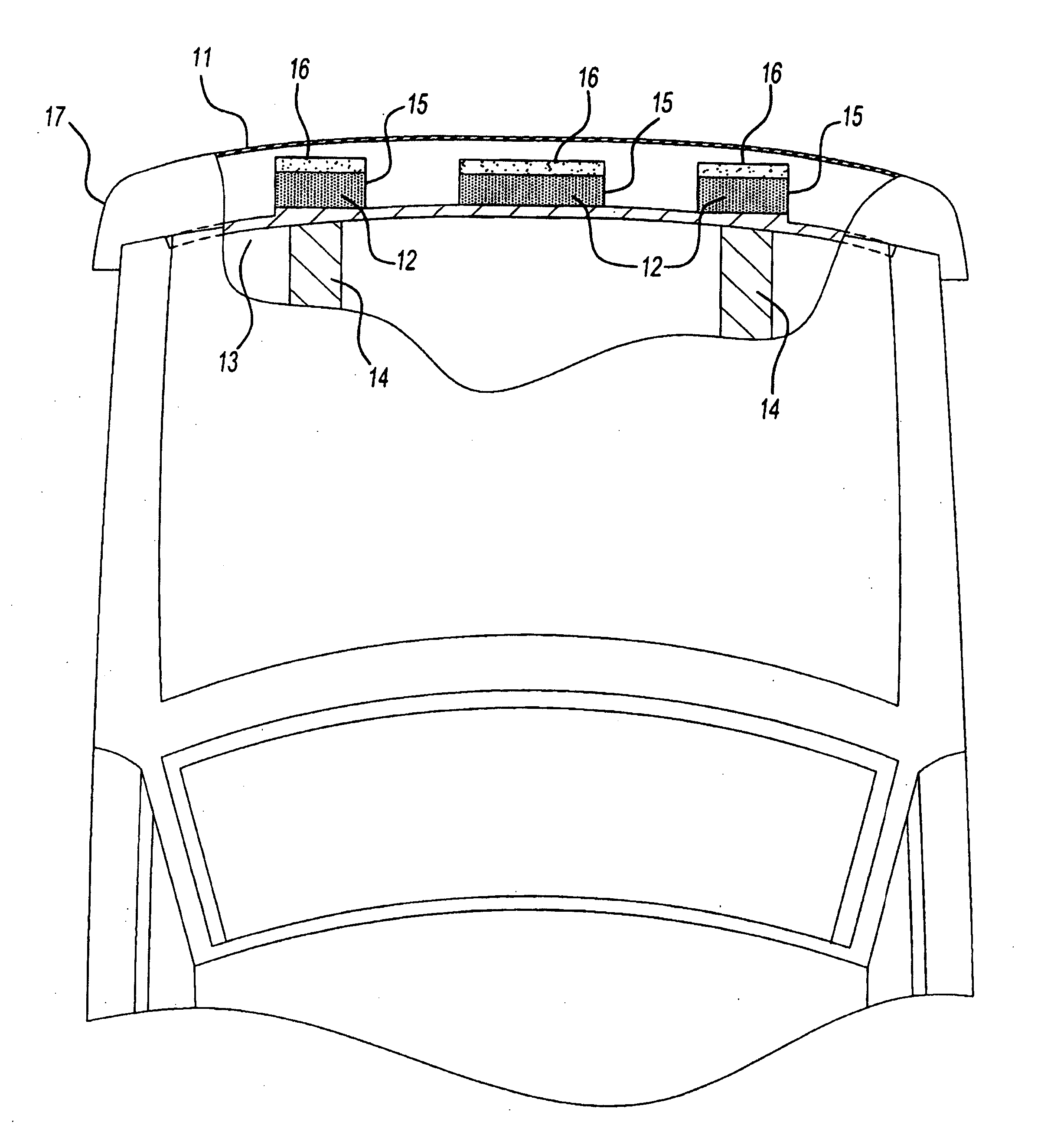
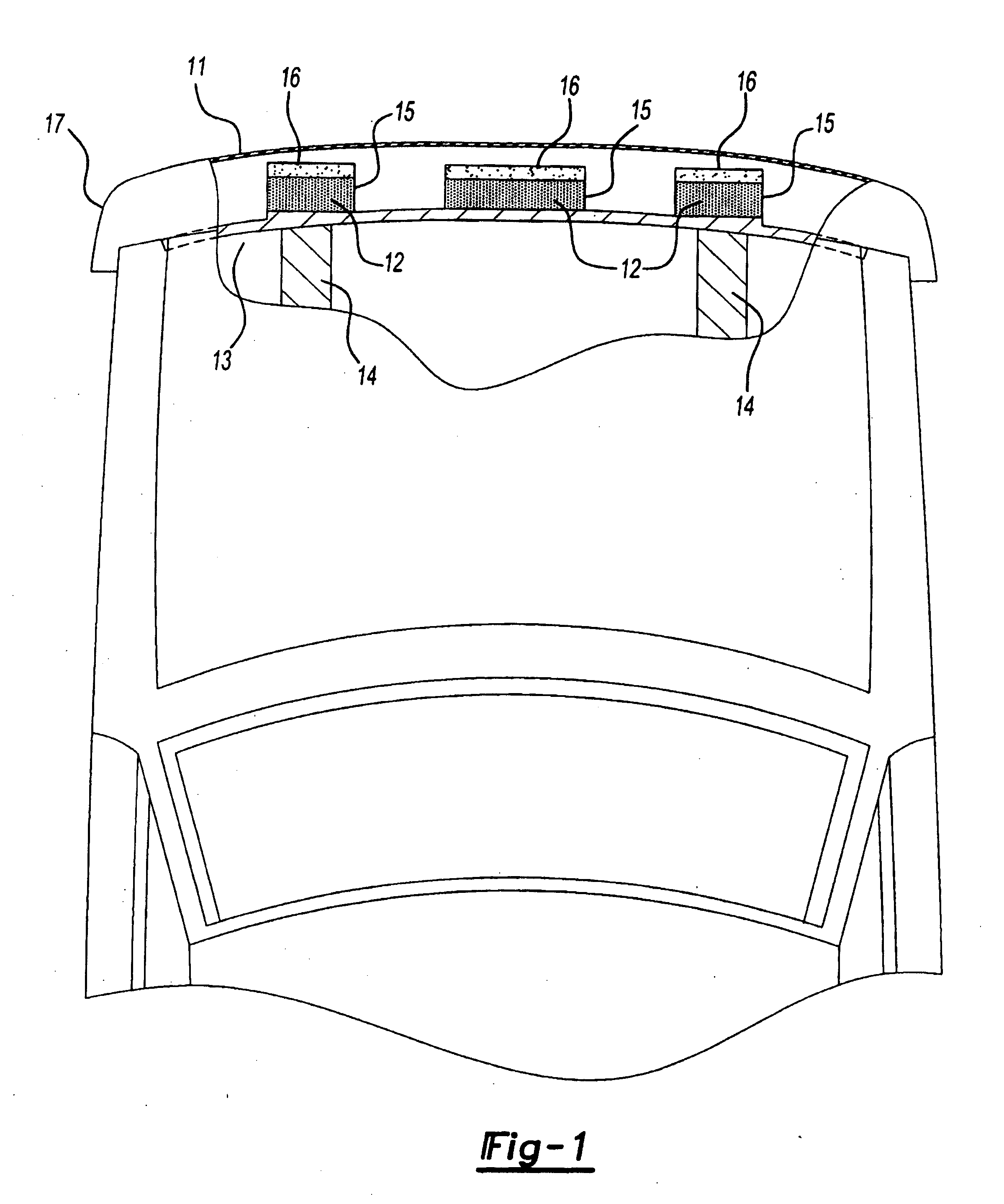
Image

Examples
specific embodiments
[0069] The following examples are provided to illustrate the invention, but are not intended to limit the scope thereof. All parts and percentages are by weight unless otherwise indicated.
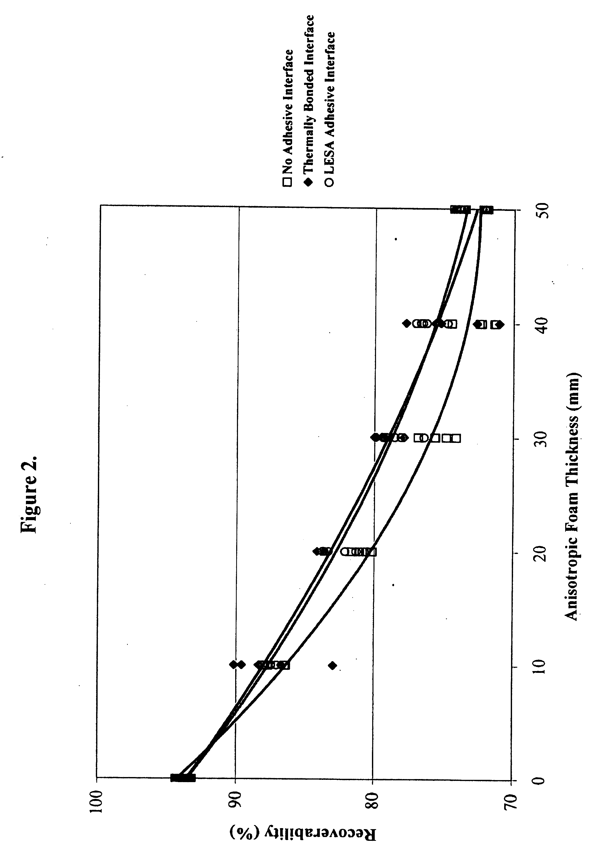
[0070] A series of quasi-static and dynamic compression tests were performed on composite foam blocks which consisted of varying levels of 46.6 kg / m3 isotropic expanded polypropylene (EPP) bead foam and 37.3 kg / m3 anisotropic polypropylene (PP) foam. The density for each material was reported as the mean of five samples that were measured and weighed to compute the specimen density. In addition, composite blocks were joined together using the following methods to simulate potential manufacturing methods: no adhesive interface, Low Energy Surface Adhesive (LESA) interface, and thermally bonded interface. For those samples that were not adhered, the perimeter of the blocks were simply joined with masking tape to simulate the anisotropic foam block being press fit into an isotropic foam cavity. Therm...
PUM
| Property | Measurement | Unit |
|---|---|---|
| Strength | aaaaa | aaaaa |
| Anisotropy | aaaaa | aaaaa |
| Surface energy | aaaaa | aaaaa |
Abstract
Description
Claims
Application Information