

Bidirectional buck-boost power converters, electric starter generator system employing bidirectional buck-boost power converters, and methods therefor
a power converter and bidirectional technology, applied in the direction of motor/generator/converter stopper, dynamo-electric converter control, electric controller, etc., can solve the problems of large capacitor bank, unacceptable change in dc voltage supplied from rectifier to load, and high ac impedan
- Summary
- Abstract
- Description
- Claims
- Application Information
AI Technical Summary
Benefits of technology
Problems solved by technology
Method used
Image

Examples
Embodiment Construction
[0011] The present invention will be explained in further detail by making reference to the accompanying drawings, which do not limit the scope of the invention in any way.
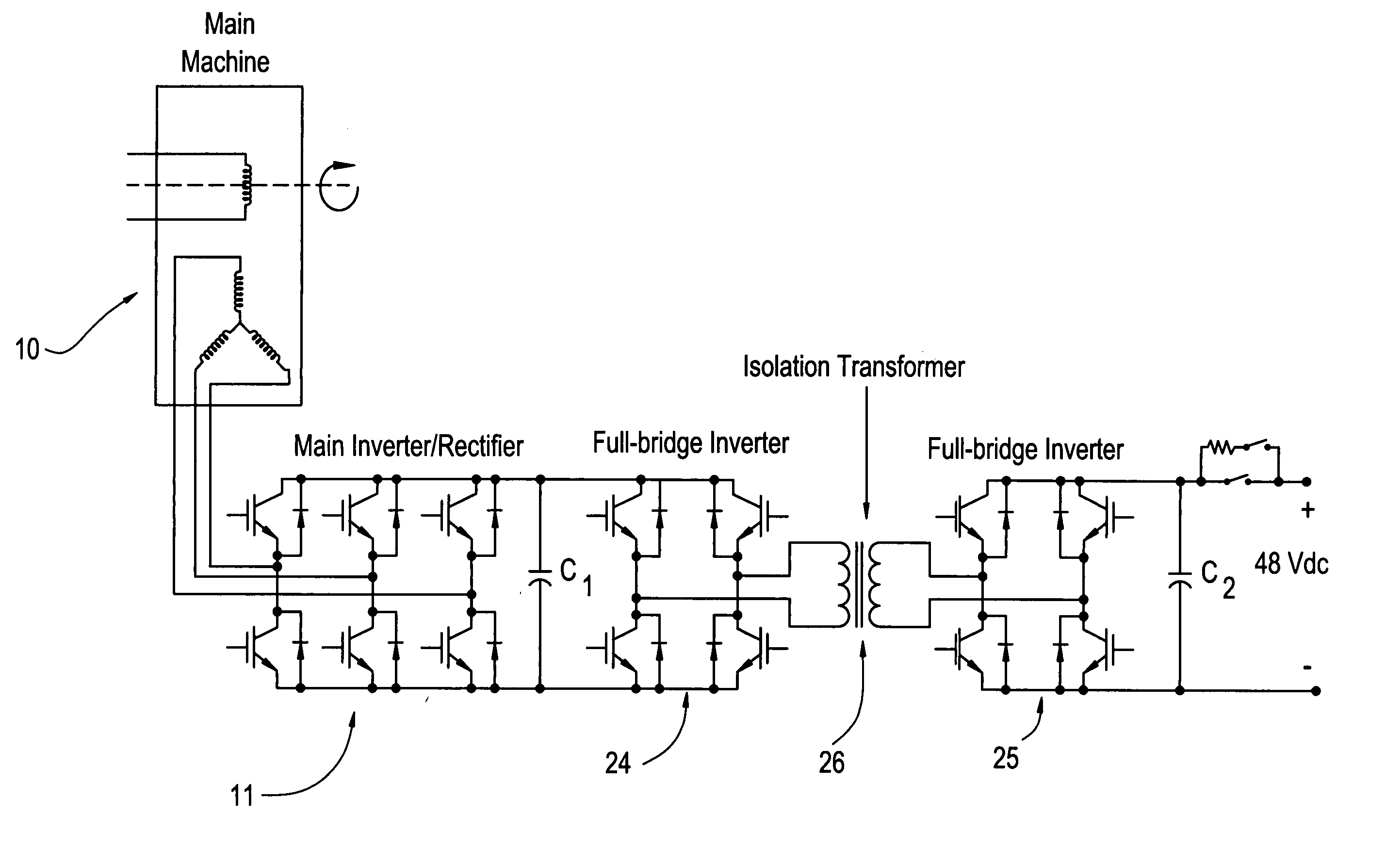
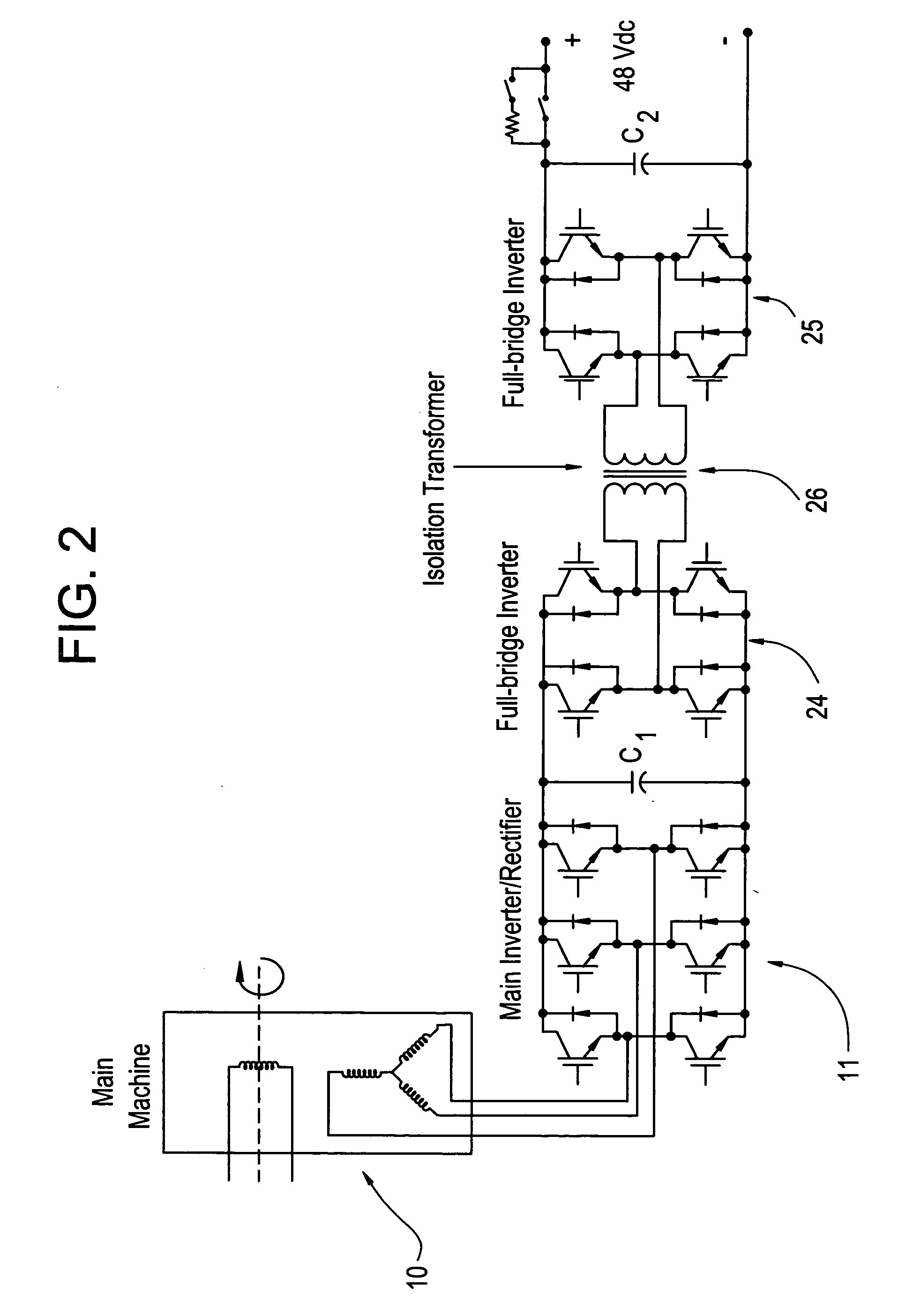
[0012] In an embodiment of the invention, two bi-directional buck-boost converters are configured at the output of an AC machine / inverter / rectifier system to allow controlled power flow in either direction, for starting or generating, while enabling fast transient response for sudden load changes. Since the voltage can be bucked or boosted in either direction, the output voltage can be maintained during a sudden load application or load removal, through control of the buck-boost converters.
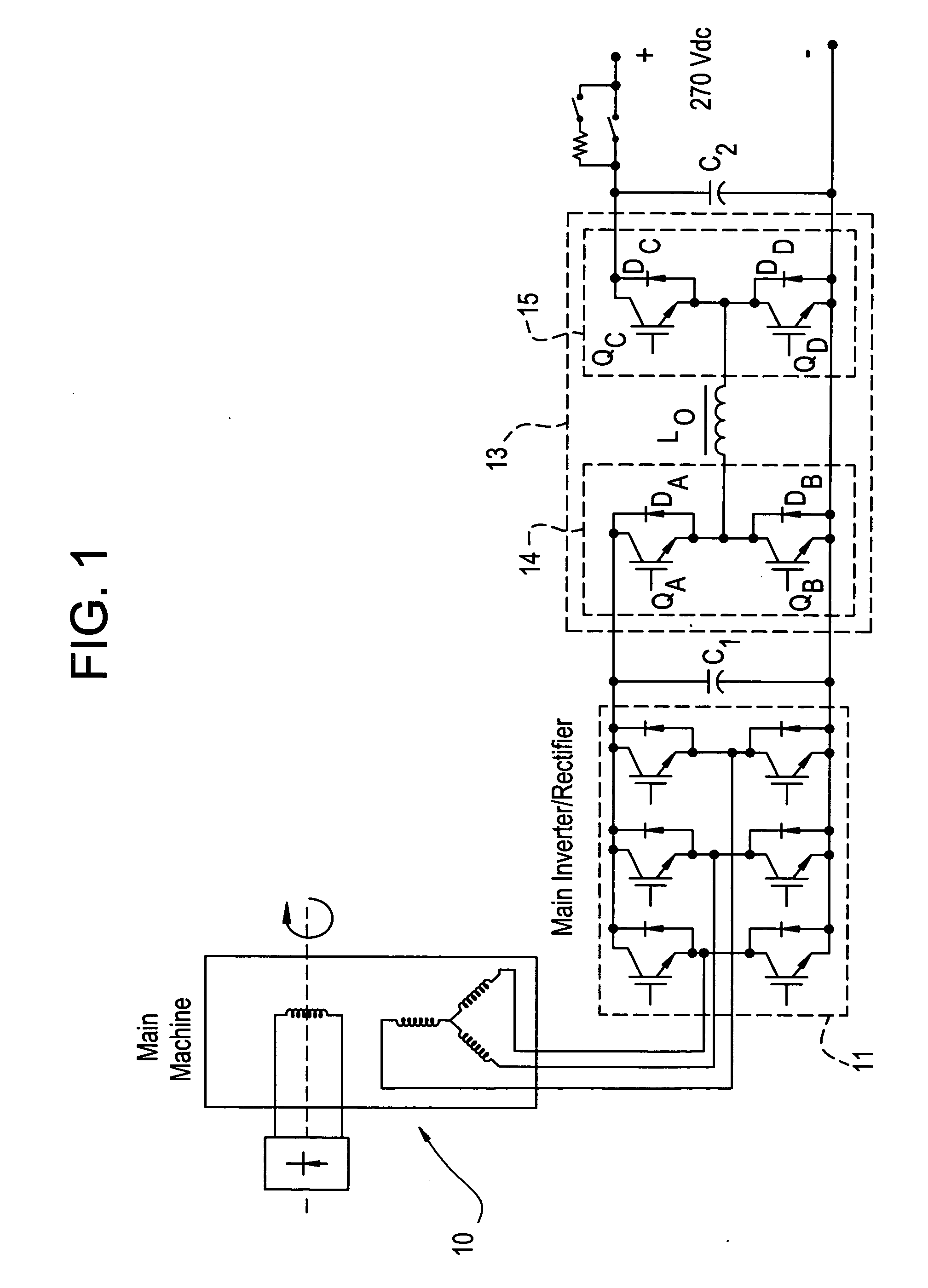
[0013] A bidirectional buck-boost power converter embodiment is described with reference to FIG. 1. Although adaptable to both DC and AC machines, the exemplary bidirectional buck-boost power converter circuit 13 discussed with reference to FIG. 1 is configured for an AC machine. FIG. 1 illustrates an AC machine 10 having a 3-...
PUM
 Abstract
Description
Claims
Application Information