Method and system for controlling an X-ray imaging system

a technology of x-ray imaging and control method, applied in the field of x-ray imaging system, can solve the problem of reducing the detector dynamic range required

Active Publication Date: 2006-05-18
GENERAL ELECTRIC CO
View PDF2 Cites 19 Cited by
  • Summary
  • Abstract
  • Description
  • Claims
  • Application Information

AI Technical Summary

Problems solved by technology

This results in a more uniform radiation flux profile and reduces the detector dynamic range required.
However, the known detector systems may still require a minimum dynamic range of at least 1,000,000:1 to adequately detect the variations in the X-ray radiation fluxes impinging on the detector systems.

Method used


Image

  • Method and system for controlling an X-ray imaging system
  • Method and system for controlling an X-ray imaging system
  • Method and system for controlling an X-ray imaging system

Examples


Embodiment Construction

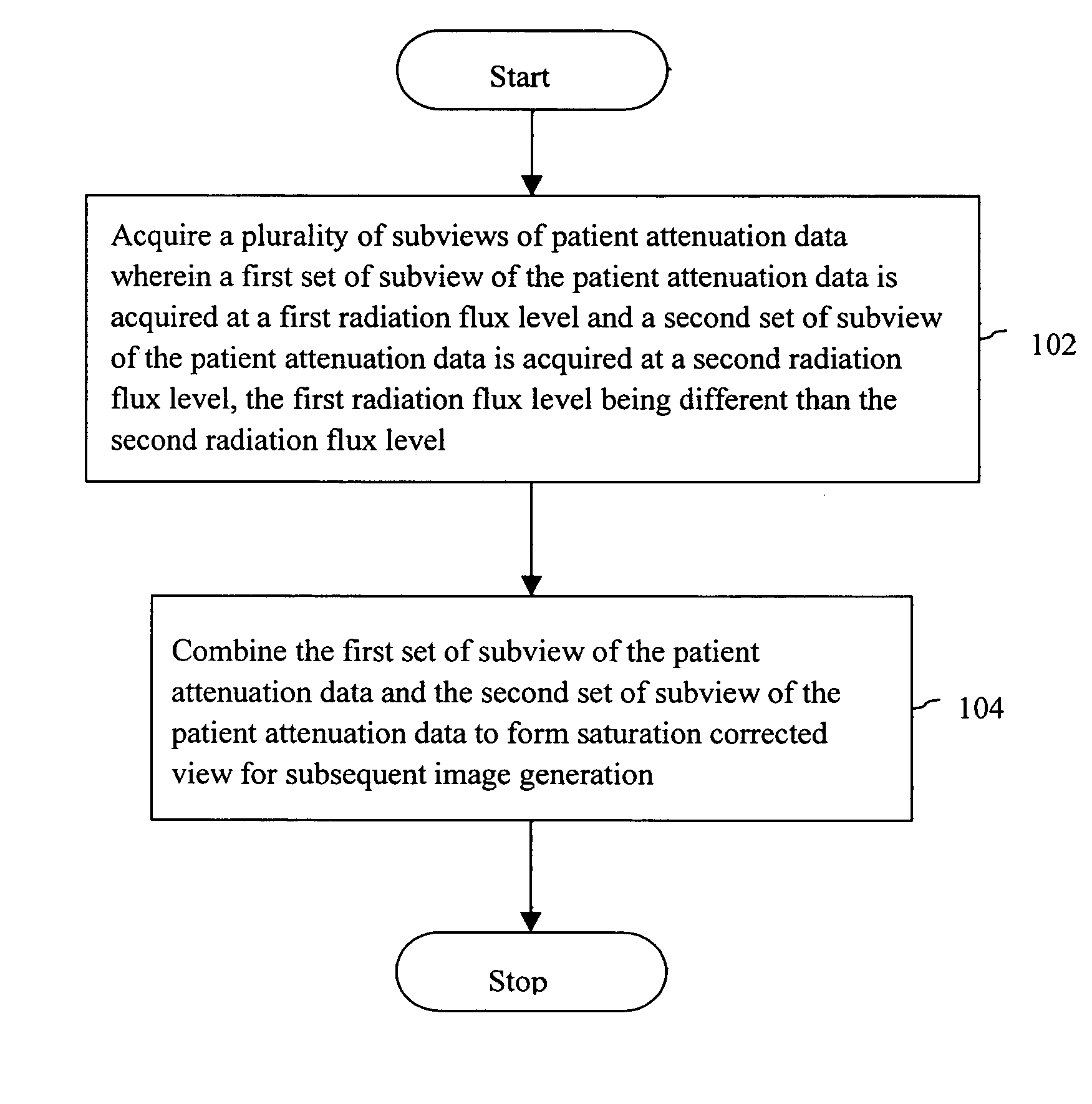
[0011] Various embodiments of the invention provide a method for controlling an X-ray imaging system. The X-ray imaging system may be, for example, a Computer Tomography (CT) scanner, and / or an X-ray scanner.

[0012]FIG. 1 is a flowchart illustrating a method for controlling an X-ray imaging system in accordance with an exemplary embodiment of the invention. At 102, a plurality of subviews of patient attenuation data is acquired at different radiation flux. A first set of subviews of the patient attenuation data is acquired corresponding to a first radiation flux level and a second set of subviews of the patient attenuation data is acquired corresponding to a second radiation flux level, wherein the first radiation flux level is different than the second radiation flux level. At 104, the first set of subviews and second set of subviews of the patient attenuation data are combined to form saturation corrected views for subsequent image generation. The saturation may occur for values o...


PUM


Abstract

Methods and systems for controlling an X-ray imaging system. The method for controlling an X-ray imaging system includes acquiring a plurality of subviews of patient attenuation data wherein a first set of subviews of patient attenuation data is acquired at a first radiation flux level and a second set of subviews of patient attenuation data is acquired at a second radiation flux level. The first radiation flux level is different than the second radiation flux level. The method further includes combining the first set of subviews of patient attenuation data and the second set of subviews of patient attenuation data to form corrected views for subsequent image generation.

Description

BACKGROUND OF THE INVENTION [0001] This invention relates generally to X-ray imaging systems and more particularly, to methods of controlling X-ray imaging systems. [0002] In X-ray imaging systems, detector systems may be exposed to a wide range of X-ray radiation fluxes during an exposure that may be due to variations in a patient anatomy and variable X-ray acquisition settings. The wide range of the X-ray flux may require a detector system with a large dynamic range such that the detector system response to relatively high X-ray flux and relatively low X-ray flux are both within predetermined specifications. At least some known X-ray imaging systems use techniques such as surrounding the patient with a water bag or placing “bowtie” filters in the X-ray beam to reduce the required dynamic range of the detector systems. The “bowtie” filters are placed in the X-ray beam to selectively shape the X-ray beam radiation flux to inversely match the patient cross-section. Further, more radi...

Claims


Application Information

Patent Timeline
Patent Type & Authority Applications(United States)
IPC IPC(8): G06K9/00G06K9/36
CPCA61B6/542A61B6/583A61B6/585
Inventor ARENSON, JEROME STEPHENRUIMI, DAVIDMEIRAV, ODEDARMSTRONG, ROBERT HARRY
Owner GENERAL ELECTRIC CO
Why Eureka
Try Eureka