
Container bag

a technology for containers and bags, applied in the field of containers, can solve the problems of large damage risk of said reinforcement wall, which is made as an accessory, and large space between the bags remaining unused, and achieves the effect of relatively small risk of load contamination

Inactive Publication Date: 2006-05-18
COMBES TRADING
View PDF10 Cites 9 Cited by
  • Summary
  • Abstract
  • Description
  • Claims
  • Application Information

AI Technical Summary

Benefits of technology

[0020] Moreover, manufacturing a container bag according to the invention is relatively simple, since the outside of the cylindrical wall part is easily accessible to provide the accessories on it.
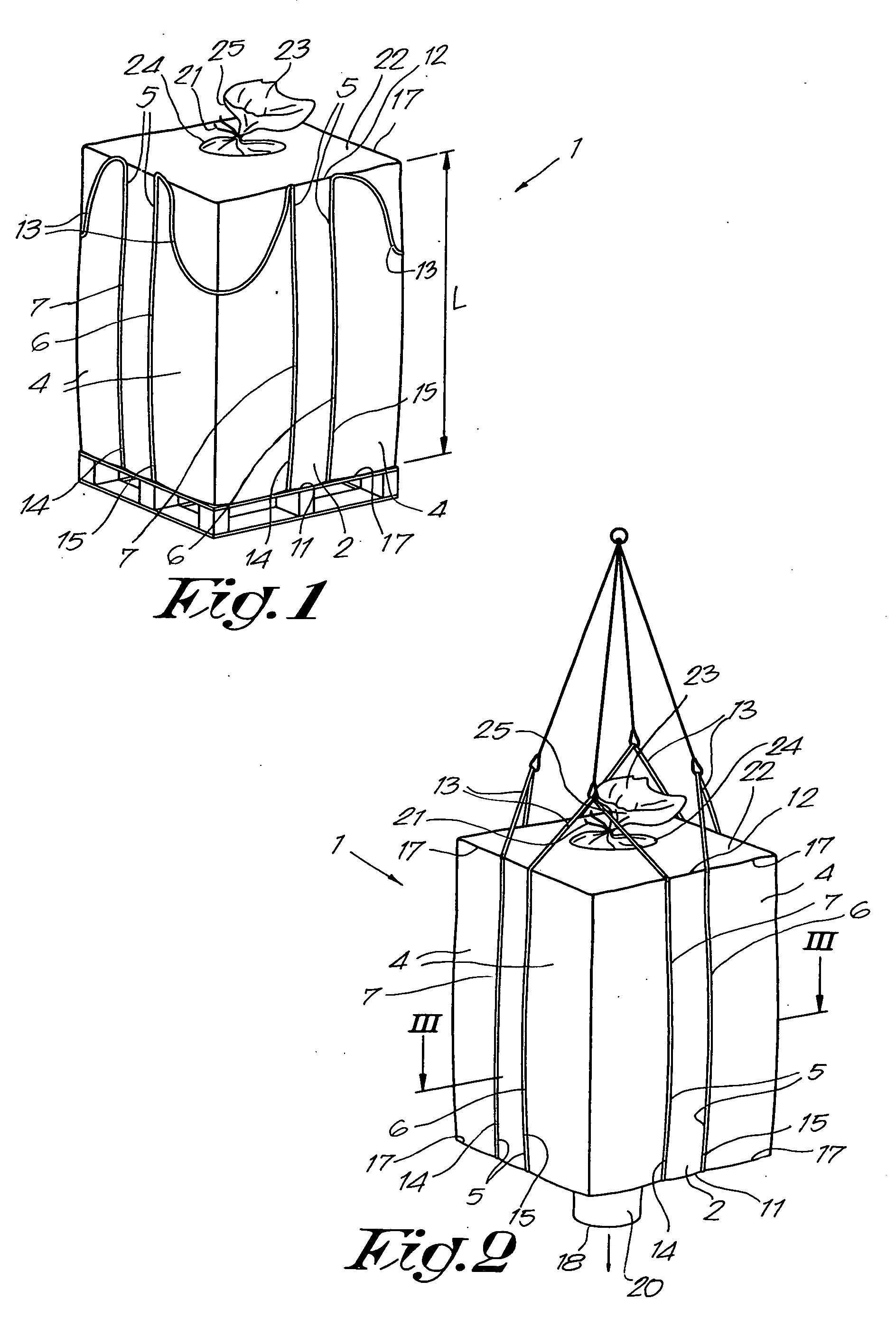
[0021] In a preferred embodiment of a container bag according to the invention, the container bags are provided with loops or the like which make it possible to lift the container bag to transport or to discharge it.
[0023] Such an embodiment offers the advantage that, when lifting the container bag, it can be discharged smoothly and efficiently.
[0024] Indeed, when a container bag according to the above-described embodiment is lifted by its loops, a strong deformation of the container bag is avoided, such that any material being discharged from additional filling spaces between the accessories and the central wall part is made difficult.
[0027] Another advantage of a container bag according to the invention is that all the stitches of the accessories on the outside of the cylindrical wall part are situated outside the filling spaces, such that the risk of contamination of the load is relatively small.

Problems solved by technology

Such known container bags are disadvantageous in that, when filled, they mainly assume a cylindrical shape, whereby the walls will bulge somewhat in the height, as a result of which, when such container bags are stacked against each other, a lot of space between the bags remains unused.
A disadvantage of such known container bags, however, is that the reinforcement wall is extremely loaded on the inside as the load in the inner filling space is the largest, as a result of which the risk of said reinforcement wall, which is made as an accessory, being damaged is relatively large.
Another disadvantage of such known container bags is that the fastening seams or the like, where the reinforcement wall is fixed to the outer bag, are situated in the filling spaces of the container bags, as a result of which the load of these container bags can possibly be soiled by fibres or yarn with which the reinforcement wall is fixed to the outer bag, which may be very undesirable when storing very pure components.
Another disadvantage of such container bags is that they are made of four bands of fabric which each form one side of the outer bag and which are initially connected by fixing the accessories, after which the four bands of fabric are fixed to each other with their adjoining edges.

Method used


Image

  • Container bag
  • Container bag
  • Container bag

Examples


Embodiment Construction

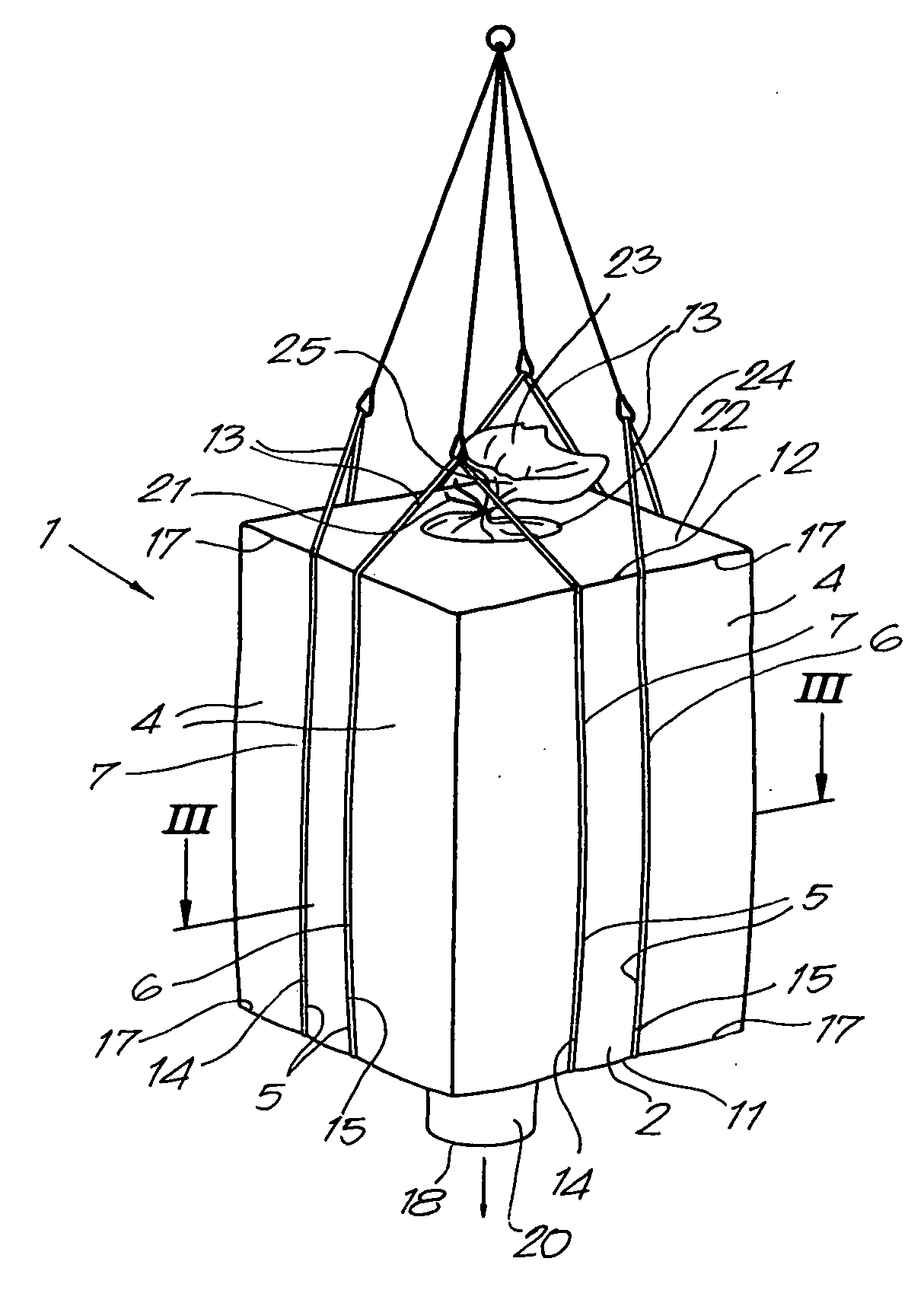
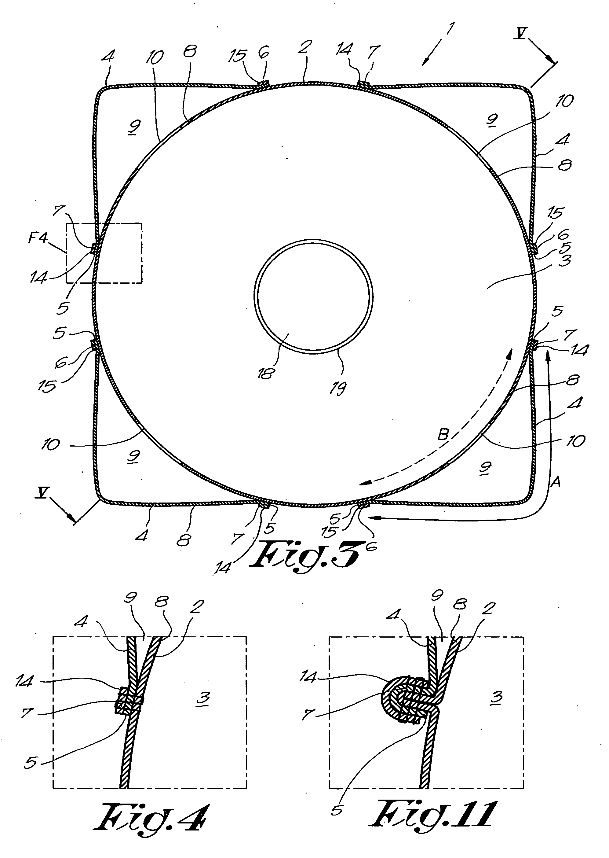
[0037] FIGS. 1 to 3 represent a container bag 1 according to the invention which mainly consists, when filled, of a cylindrical wall part 2 forming a filling space 3 and onto which are provided, on the outside, different accessories 4.

[0038] The wall part 2 as well as the accessories 4 are usually made of a fabric, whereby the accessories 4 are in this case rectangular or practically rectangular bands which are fixed to the wall part 2 with their longitudinal sides 5 in the longitudinal direction X-X′ of the cylindrical wall part 2, for example by means of stitching, stapling, gluing or the like.

[0039] As is represented more in detail in FIG. 4, the accessories 4 are in this case fixed to the wall part 2 by means of stitching, whereby we can distinguish two fastening seams 6-7 per accessory 4.

[0040] According to the invention, the width A of the accessories is larger than the peripheral distance B between both fastening seams 6-7, measured along the edge of a part 8 of the cylind...


PUM


Abstract

Container bag which comprises, when the container bag is filled, a cylindrical wall part forming a first central filling space; a number of accessories fixed thereto forming additional filling spaces; and a bottom, wherein the above-mentioned accessories are provided on the outside of the cylindrical wall part.

Description

BACKGROUND OF THE INVENTION [0001] 1. Field of the Invention [0002] The present invention concerns a container bag. [0003] A container bag is a flexible packaging for bulk products such as powders, granulated material, liquids and viscous substances or the like. [0004] Such container bags are available in different dimensions and measures of volume, and they are made of supple materials which are fixed to each other by means of sewing, welding, gluing or any other connecting techniques whatsoever. [0005] The container bags have a bottom and possibly a cover which can be made in the form of a sealing cloth or in the form of an either or not conical feed valve which is formed by a narrowed part in the cover. [0006] 2. Discussion of the Related Art [0007] The bottom of the known container bags can be made as a flat, sealed bottom or as a discharge valve which is formed by a narrowed part in the bottom and which can be sealed as desired by tying it up or the like. [0008] Such known cont...

Claims


Application Information

Patent Timeline
IPC IPC(8): B65D30/22B65D33/14B65D33/00B31BB65DB65D33/12B65D88/16
CPCB65D88/1618B65D88/1631B65D88/1668B65D88/1681
Inventor COMBES, JOHAN HENDRIK MARIA
Owner COMBES TRADING
Learn More