Kit for implanting heat deformable fixation elements of different sizes

a technology of fixation elements and kits, applied in the field of kits for implanting fixation elements of different sizes, can solve the problems of reducing the effect of the fixation element anchoring procedure, determining the optimal amount of energy needed, and irradiation duration

Active Publication Date: 2015-06-16
DEPUY SYNTHES PROD INC
View PDF37 Cites 3 Cited by
  • Summary
  • Abstract
  • Description
  • Claims
  • Application Information

AI Technical Summary

Benefits of technology

[0007]The kit of the invention provides the advantage of higher security and reduced possibilities of error due to an automatic selection of the optimal energy duration relative to the size of the fixation element. The kit of the invention also offers convenient operation with a smaller risk of contamination when changing a tip thereof. That is, since the entire disposable tip is changed between procedures, the possibility of cross-contamination via, for example, a contaminated optical fiber, is substantially reduced and / or eliminated.
[0008]The volume of the fixation element according to the invention (e.g., a bone fixation pin) is preferably in a range of about 4 mm3 to about 400 mm3 and the surface of the fixation element is preferably in a rage of 2 mm2 to 240 mm2. The optical waveguides of the light guiding tip are connected to the optical waveguides of the hand piece and configured to operate at full power, the total energy transmitted to the fixation element being controlled by the optical waveguides of the exemplary kit of the invention. A laser source connected to the hand piece can be provided with an internal power supply (e.g., a battery or an accumulator) or can comprise a connecting cable to an external electric network. A further advantage of the kit according to the invention is that the interface can be remote from the surgical intervention site.
[0021]In yet another embodiment of the kit, two or more light guiding tips comprise fixation elements of different sizes and respectively different set-point means that define the time period tV for the timer or induce the microprocessor to control the magnitude of radiant flux ΦV of the laser source. This embodiment has the advantage that the different fixation elements attached to the light guiding tips are heated up by transmission of an individually defined total radiant energy.
[0032]The term laser types, as used in the description, refers to lasers that typically emit only a few narrowly defined frequencies of electromagnetic radiation. The absorption spectra of one or more chromophores of the non-absorbing portion of the fixation element as well as of surrounding tissue may thus be selected to be attuned to one other. In a preferred application, the laser radiates in a preferably monochromatic frequency that is barely absorbed by the implant, strongly by the chromophore, and again only barely by the surroundings. This makes it possible to supply different areas with different chromophores in the implant, and to specifically warm them up with the electromagnetic radiation frequency that may be preferred on a case-by-case basis.

Problems solved by technology

However, present fixation elements prevent a determination of an optimal amount of energy needed to properly anchor the fixation element in the bone, instead relying only on rough estimates based on various parameters (e.g., thermoplastic material, volume of the fixation element, absorptive properties of the thermoplastic material or possibly contained chromophores therein, and power of the light source).
The subjective estimation can lead to an irradiation duration that is either too short or too long, thus reducing an efficacy of a fixation element anchoring procedure.
Specifically, if the irradiation period is too short, the fixation element undergoes an insufficient softening and is unable to adapt to a shape of a bone or other environment in which it is implanted, thus causing a poor anchorage.
If the irradiation period is too long, an excessive liquefaction of the fixation element results, permanently damaging the mechanical stability of the fixation element.
Furthermore, depending upon the supplied excessive quantity of energy, over-irradiation can also lead to an overheating of the thermoplastic material to further reduce an anchoring strength of the fixation element in the bone.

Method used


Image

  • Kit for implanting heat deformable fixation elements of different sizes
  • Kit for implanting heat deformable fixation elements of different sizes
  • Kit for implanting heat deformable fixation elements of different sizes

Examples


Embodiment Construction

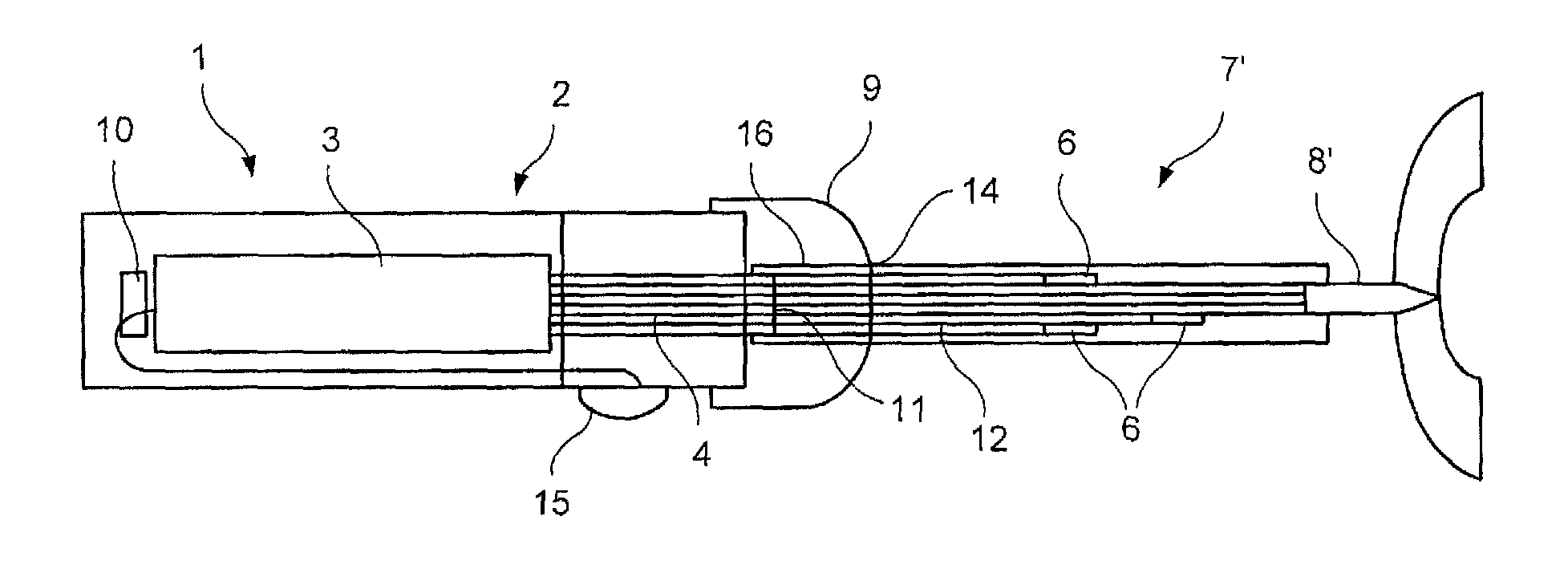
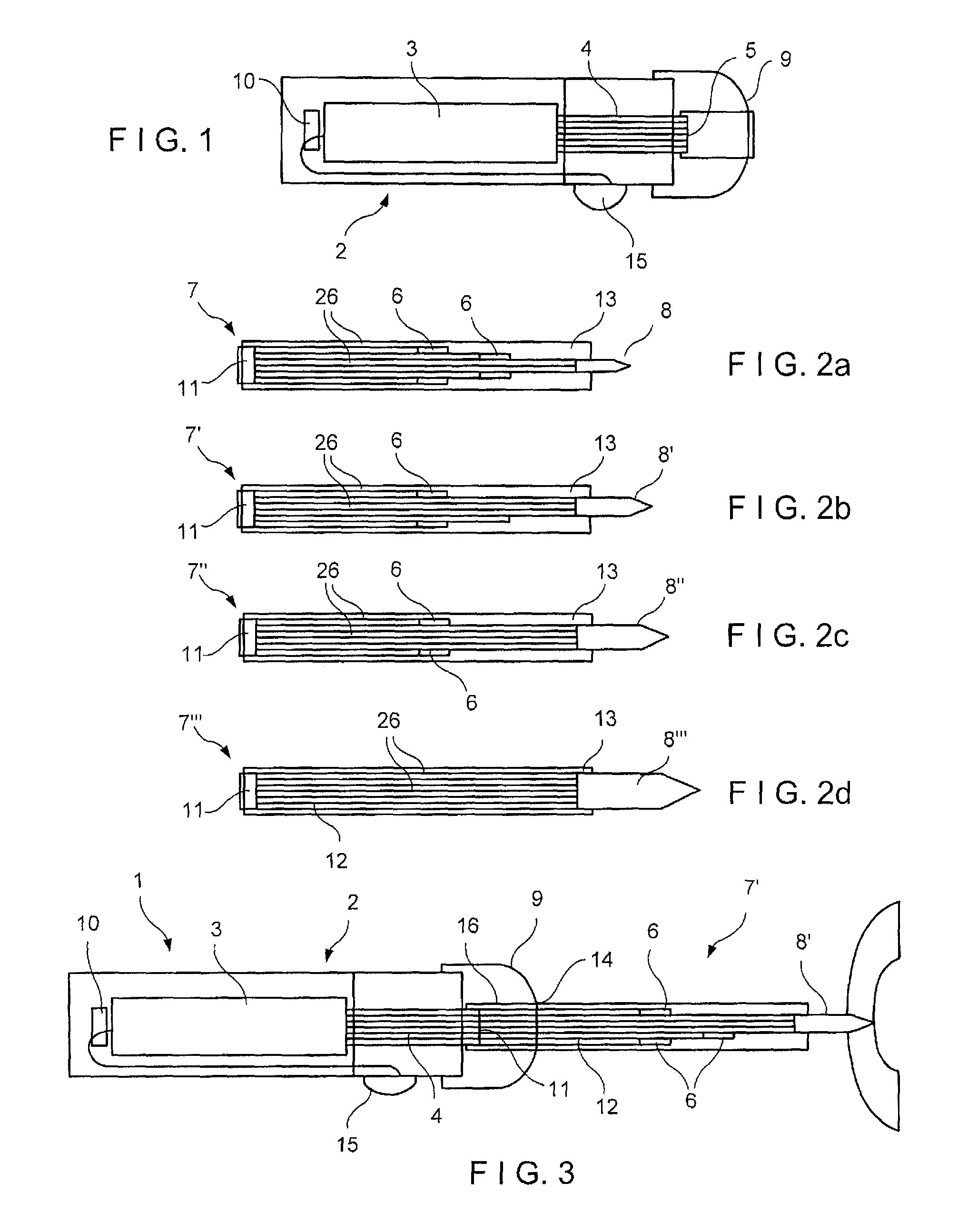
[0081]The present invention is directed to a system and method for the fixation of a bone by implanting a device into the bone, a portion of the device including a material configured to be softened upon application of heat to aid in anchoring the device to the bone. In particular, the present invention is directed to a device comprising one or more bone fixation elements formed of, for example, a biocompatible polymer having material properties (e.g., color, reflective coating, etc.) configured to aid in fixation thereof in a target location of the bone. The exemplary system and method according to the invention also comprises a handpiece configured to guide insertion of the fixation element to a target portion of the bone. The exemplary handpiece is configured to transport laser light from a laser light source provided therein to one or more light guiding tips operably connected thereto. The light guiding tips further guide the laser light to the fixation elements. As will be desc...


PUM


Abstract

A device for implanting heat deformable fixation elements of different sizes in a bone, comprises a hand piece extending from a proximal end to a distal end and including an internal optical waveguide connected to a laser source and open to the distal end of the hand piece and a light guiding tip extending from a proximal end to a distal end, the proximal end of the light guiding tip being removably mechanically and optically connectable to the distal end of the hand piece and the distal end of the light guiding tip being configured to permit removable attachment of a bone fixation element, the light guiding tip including an optical waveguide, wherein the light guiding tip is configured to control a total radiant energy Q transmitted from the laser source to the bone fixation element.

Description

PRIORITY CLAIM[0001]The present application claims priority to U.S. Provisional Application Ser. No. 61 / 424,949 entitled “Kit for Implanting Heat Deformable Fixation Elements of Different Sizes” filed on Dec. 20, 2010, the entire disclosure of which is incorporated herein by reference thereto.FIELD OF THE INVENTION[0002]The present invention generally relates to a kit for implanting fixation elements of different sizes in a bone. More particularly, the present invention relates to a kit for implanting heat deformable fixation elements of different sizes.BACKGROUND OF THE INVENTION[0003]Fixation elements (e.g., pegs, screws, pins) are well known in the field of bone fixation and consist completely or partly of thermoplastic materials which can be softened or melted completely or preferably at their surface by application of electromagnetic radiation (e.g. laser light) thereto. Softening or melting of the thermoplastic material permits the fixation elements to adapt their shape to a s...

Claims


Application Information

Patent Timeline
Patent Type & Authority Patents(United States)
IPC IPC(8): A61B18/20A61B17/88A61B18/22
CPCA61B17/8863A61B18/20A61B18/22A61B17/8872A61B2018/2285A61B17/866A61B2018/00565A61B2018/00702A61B2018/202A61B2018/2222
Inventor HULLIGER, URS
Owner DEPUY SYNTHES PROD INC
Why Eureka
Try Eureka