Deposition burner and method for the manufacture thereof, use of the deposition burner and method for the production of a quartz glass body by using the deposition burner

a technology of deposition burner and burner, which is applied in the direction of glass deposition burner, glass tempering apparatus, furnace, etc., can solve the problems of troublesome compensation, complex fabrication and orientation of individual quartz glass tubes, and variation of material axial geometrical and inhomogeneousness, and achieves small manufacturing tolerance, low cost, and low risk of contamination during intended use.

Active Publication Date: 2010-06-03
HERAEUS QUARZGLAS
View PDF11 Cites 14 Cited by
  • Summary
  • Abstract
  • Description
  • Claims
  • Application Information

AI Technical Summary

Benefits of technology

[0014]It is therefore the object of this invention to provide a deposition burner, and a method for the manufacture thereof, which can be manufactured with small manufacturing tolerances at low costs and in the case of which the risk of contamination during the intended use is small at the same time. Furthermore, it is the object of the present invention to indicate a suitable use of the deposition burner according to the invention as well as a reproducible method for making a homogeneous body of synthetic quartz glass by using a flame hydrolysis burner according to the invention.

Problems solved by technology

Especially with blanks consisting of porous quartz glass (so-called “soot bodies”), particular attention is paid that all of the deposition burners show deposition characteristics that are as uniform as possible because, otherwise, this would result in a locally irregular soot density or soot quantity, which leads to axial geometric variations and inhomogeneities of the material and to disturbances particularly in the contact area between neighboring deposition zones.
On the other hand, precise fabrication and orientation of the individual quartz glass tubes is complicated, especially when traditional glass-blowing methods have to be employed.
Likewise, it is troublesome to compensate for possible differences in the burner characteristics by positioning the deposition burners individually.
For series manufacture specifically adapted tools are normally used, the production of which presents a considerable cost factor.
A complex burner construction requires the provision of a great number of such tools that, however, as has been shown, are subject to rapid wear due to the hardness of the metallic material, whereby the manufacturing precision is decreasing.
Moreover, contamination of the quartz glass by constituents of the high temperature-resistant metallic material must be expected in metal burners.

Method used


Image

  • Deposition burner and method for the manufacture thereof, use of the deposition burner and method for the production of a quartz glass body by using the deposition burner
  • Deposition burner and method for the manufacture thereof, use of the deposition burner and method for the production of a quartz glass body by using the deposition burner
  • Deposition burner and method for the manufacture thereof, use of the deposition burner and method for the production of a quartz glass body by using the deposition burner

Examples


Embodiment Construction

[0075]The present invention shall now be explained in more detail with reference to an embodiment and a drawing, which schematically shows in detail in

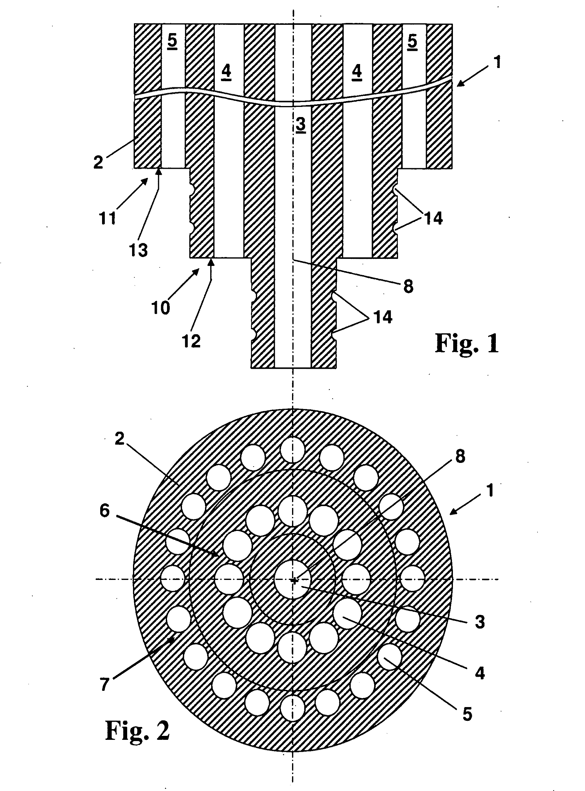
[0076]FIG. 1 the distal end of the burner head in an embodiment of the deposition burner according to the invention, in a longitudinal section;

[0077]FIG. 2 a radial cross-section of the deposition burner according to FIG. 1;

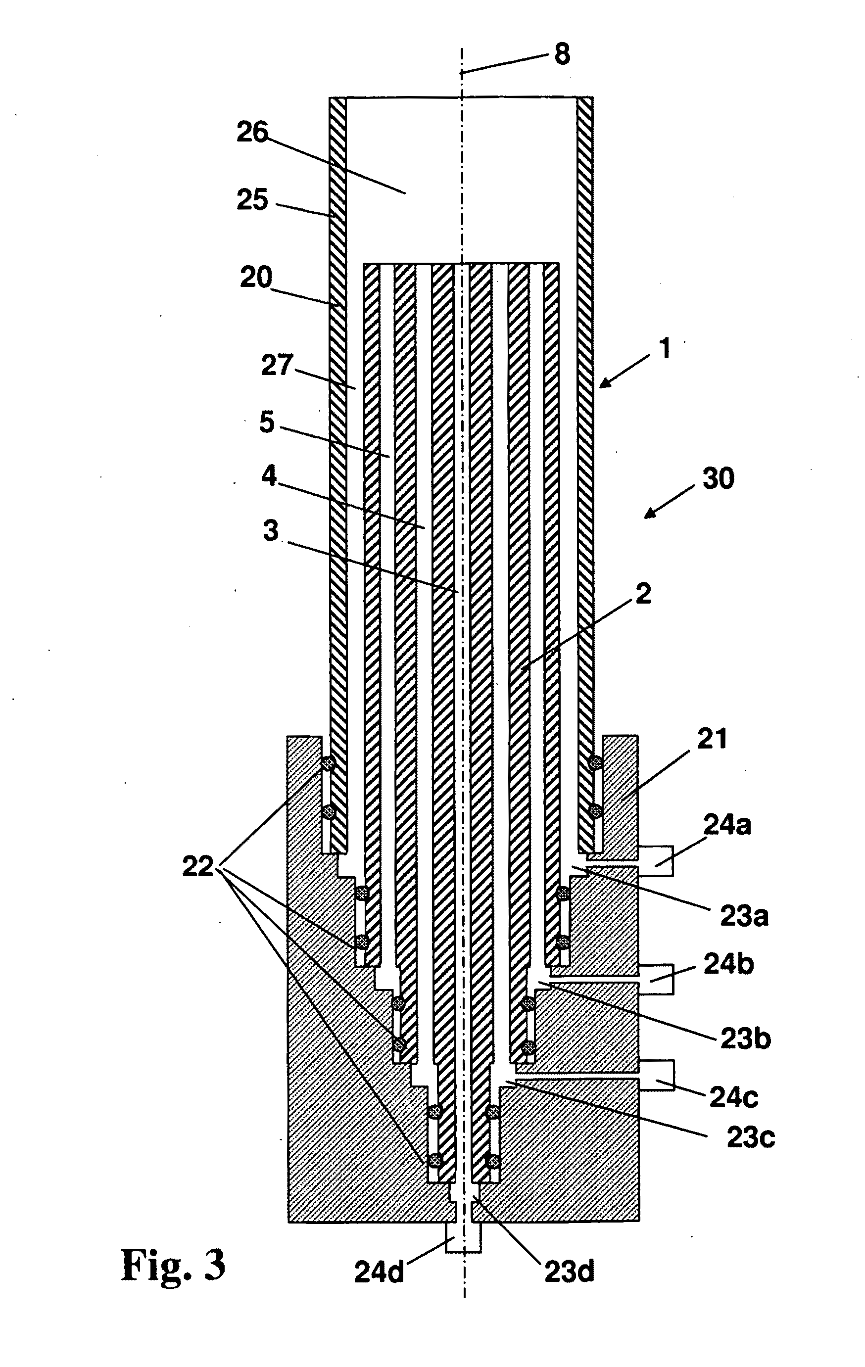
[0078]FIG. 3 an assembly drawing of the deposition burner according to FIG. 1 and FIG. 2, in a longitudinal section; and

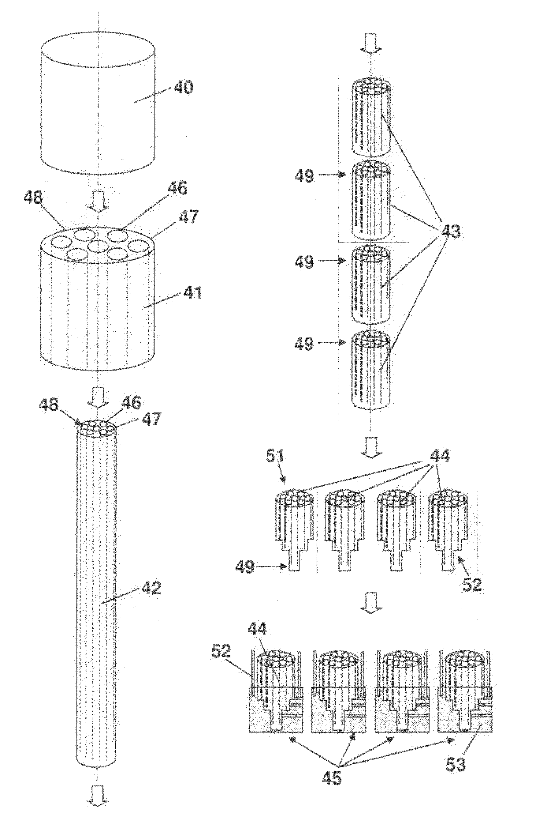
[0079]FIG. 4 a schematic illustration for explaining the process sequence in a procedure according to the invention for producing a deposition burner.

[0080]FIGS. 1 and 2 illustrate different views of the burner head 1 of an oxyhydrogen burner for producing an SiO2 soot body according to the OVD method.

[0081]The burner head 1 consists of a massive burner base body 2 of synthetic quartz glass, which is configured to be substantially in rotational symmetry with respect to the longitudinal axis 8. The...


PUM

PropertyMeasurementUnit
lengthaaaaaaaaaa
outer diameteraaaaaaaaaa

Abstract

To provide a method for the inexpensive manufacture of a deposition burner with small manufacturing tolerances for use in the synthesis of quartz glass, and wherein moreover, when the deposition burner is used as intended, the risk of contamination of the quartz glass to be produced is low, the invention suggests the following method steps: (a) providing a start cylinder of quartz glass (40) which is mechanically provided with longitudinal bores (46, 47); (b) elongating the start cylinder with formation of a burner strand (42), the longitudinal bores being shaped as elongated channels extending in parallel with one another; (c) cutting the burner strand into pieces in the form of cylindrical quartz glass blocks (43), each being provided with passage lines extending in parallel with a central axis of the quartz glass block; and (d) manufacturing the deposition burner by using a respective one of such quartz glass blocks as burner head which has a proximal end and a distal end, the passage lines serving the supply of process media from the distal to the proximal, burner head end.

Description

[0001]The present invention refers to a method for the manufacture of a deposition burner for use in the manufacture of synthetic quartz glass.[0002]Moreover, the present invention refers to a deposition burner of quartz glass for use in the manufacture of synthetic quartz glass, the deposition burner comprising a burner head having a proximal end and a distal end.[0003]Furthermore, the present invention refers to a use of the deposition burner according to the invention.[0004]Moreover, the present invention is concerned with a method for the manufacture of a body of synthetic quartz glass in that process media are supplied to a deposition burner, SiO2 particles are formed therefrom and said particles are deposited layer by layer on a carrier with formation of an SiO2 blank.TECHNICAL BACKGROUND[0005]In the manufacture of quartz glass bodies according to the so-called OVD (outside vapor deposition) method, SiO2 particles are formed by flame hydrolysis by using one or more deposition ...

Claims


Application Information

Patent Timeline
Patent Type & Authority Applications(United States)
IPC IPC(8): C03C17/00C03B23/047B05C9/14
CPCC03B19/1423C03B23/047C03B2207/52C03B2207/40C03B2207/42C03B2207/12
Inventor HUENERMANN, MICHAEL
Owner HERAEUS QUARZGLAS
Why Eureka
Try Eureka