Device for conveying bulk material

Inactive Publication Date: 2006-05-18
SHW STORAGE & HANDLING SOLUTIONS
View PDF12 Cites 11 Cited by
  • Summary
  • Abstract
  • Description
  • Claims
  • Application Information

AI Technical Summary

Benefits of technology

[0010] By using at least two drives, namely one drive for the roof and another drive for the base, the operating range of the device can be extended to cope with larger storage containers, in particular silos, and / or heavier bulk materials. As regards the preferred embodiment in which the base absorbs the reaction torque for driving the roof in rotation, it is already of advantage, irrespective of the number of motors, that the reaction torque simultaneously also constitutes the driving torque for the base and is not wasted. As the column of bulk material increases in height and the friction between the bulk material and roof increases as a result, only the reaction torque increases. As a result, the torque needed for the rotating motion decreases because the effect of overcoming the roof friction, i.e. the friction between the roof and the bulk material bearing down on it, is used to drive the rotating motion of the conveyor unit. At low filling levels and when the torque needed to drive the roof is low accordingly, on the other hand, a low reaction torque is also generated on the part of the base so that the roof drive absorbs less power accordingly and is subjected to less wear, which also applies to the bearing and the conveyor unit.
[0011] A more uniform conveying rate can also be achieved when discharging a column of bulk material as a result of the invention. If the drive generates a constant torque throughout the discharge duration, as is standard practice, the rotation speed of the conveyor unit increases as the height of the column of bulk material decreases. The filling level of the conveyor unit increases accordingly. However, if the same driving torque is split and applied to the drive for the base and the drive for the roof as proposed by the invention, the roof rotates faster as the column height decreases because the decreasing weight of the column of bulk material primarily bears on the roof. The sliding friction between the roof and the bulk material and hence also the torque transmitted from the roof to the base decrease. The rotation speed of the base primarily increases only in the same proportion as the sliding friction acting between the bulk material and the base and the weight of the bulk material acting on the conveyor unit decrease. Compared with conventional devices, acceleration due to the decreasing column height is reduced by the amount induced by the decreasing sliding friction between roof and bulk material as a result. Since the conveying rate is more uniform, the bulk material is conveyed less roughly. In order to save motor power, the desired value for the torque of the roof drive can be reduced, controlled or regulated during discharge. If the driving power is divided between several motors, one of the motors may be switched off or several motors can be switched off in succession.
[0012] Since the roof can be driven in rotation relative to the base, not only is it possible to prevent or least make it more difficult for a bridge base to form in the region of the roof with a low torque requirement for rotating the roof, the roof can additionally also be further modified so that it actively destroys any bridge foot. As part of such modifications, an effector device is disposed on the roof which destroys bridges formed by the bulk material. The effector device consists of at least one effector element which projects down from the roof parallel with the rotation axis or at least parallel with a directional component. The at least one effector element projects from an external face of the roof into the bulk material and is shaped so that, as the roof rotates, it breaks, cuts into, tears up or otherwise destroys bridges of bulk material disposed in the path of its rotating motion.
[0016] If the roof is used as a means of destroying bridge bases, the height of the column of bulk material bearing down on the roof can be further increased because bridges of bulk material are reliably destroyed.

Problems solved by technology

As the filling level rises, there is an increased risk of a stable bridge of bulk material forming.
Also in the case of conically shaped roofs and domed roofs, there is a danger of a stable bridge of bulk material forming from the vertical silo wall to the roof of the screw tower.

Method used


Image

  • Device for conveying bulk material
  • Device for conveying bulk material
  • Device for conveying bulk material

Examples


Embodiment Construction

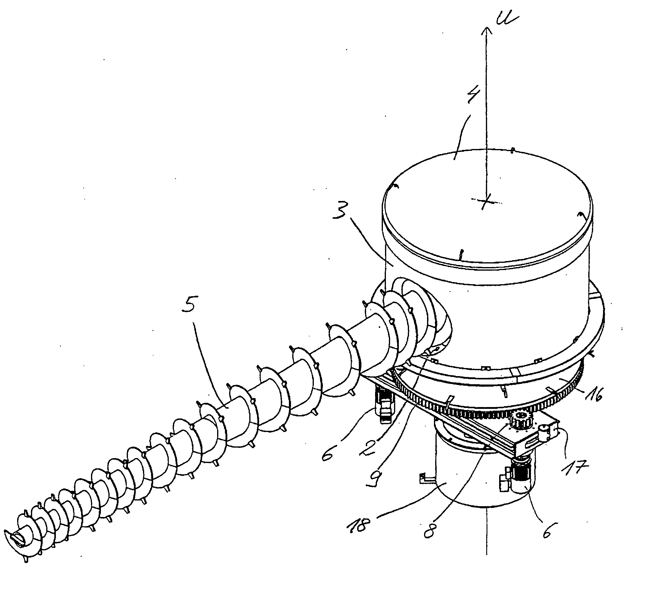
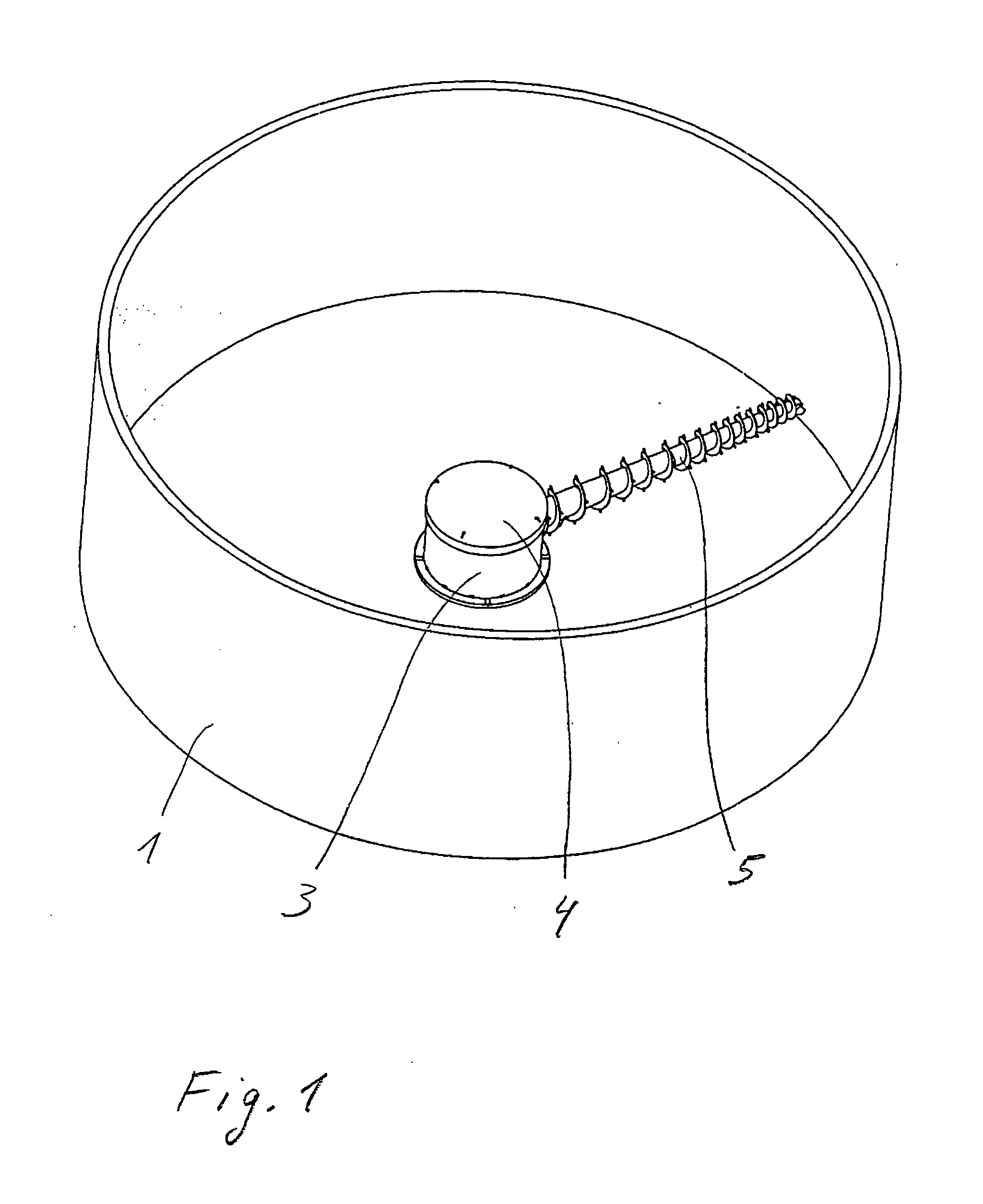
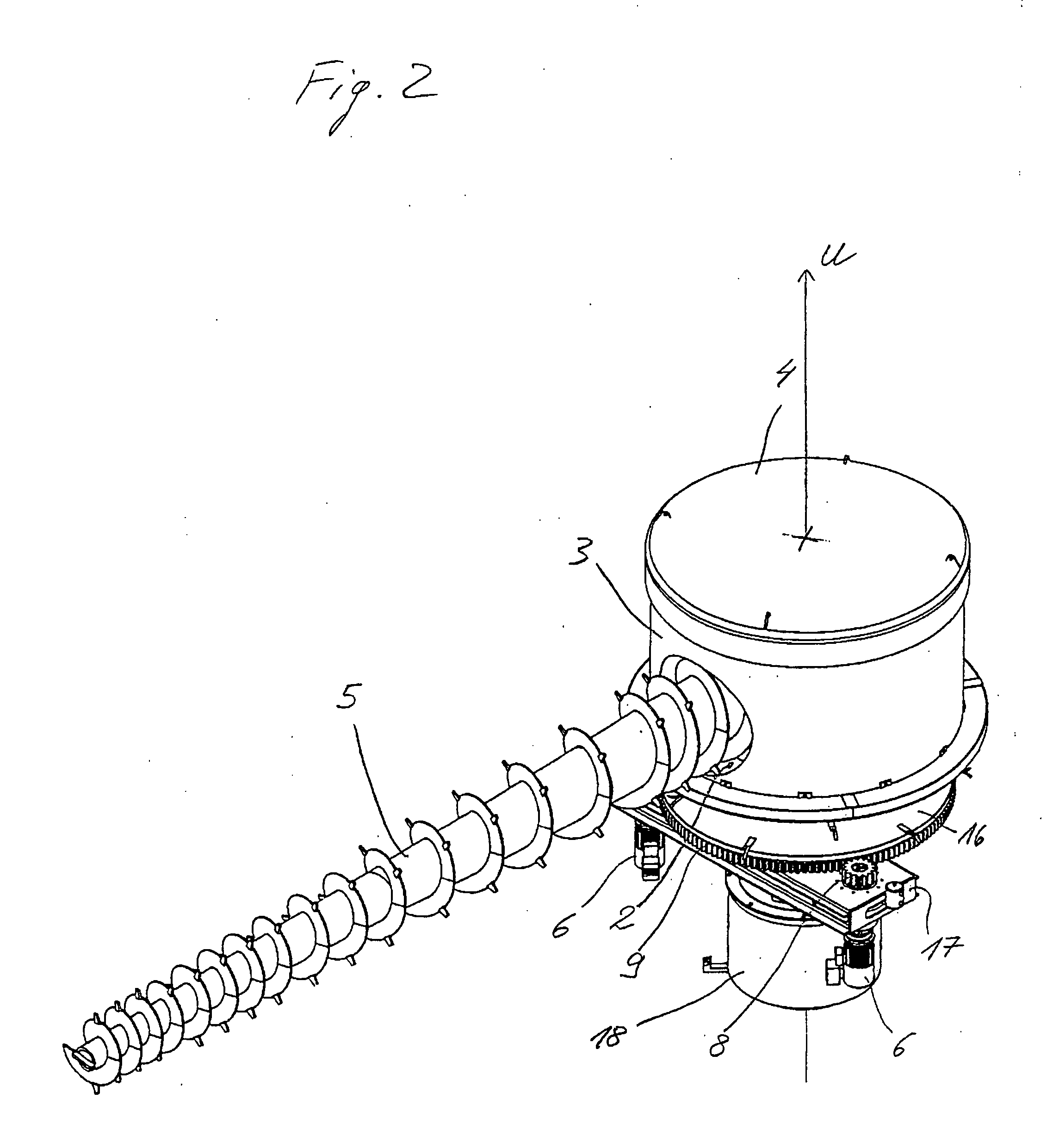
[0029]FIG. 1 shows a view down into a store for bulk materials. The bulk material store comprises a storage container, which in the embodiment illustrated here is provided in the form of a silo with a circular side wall 1. However, only one circular portion of the side wall 1 is illustrated. On a base of the storage container 1, a device for conveying bulk material is disposed at its centre. The device comprises a conveying unit 5, which in the embodiment illustrated as an example is a conveyer screw 5, as well as a tower formed by a base which is not illustrated in the drawing, a jacket 3 fixedly joined to the base so as to rotate with it and a roof 4 in the form of an at least substantially closed housing. The base is mounted on a frame of the bulk material store so that it can rotate about a vertical rotation axis U. When the tower 3, 4 is rotated, the conveyer screw 5 pivots about the rotation axis U and as it does so wipes the entire base surface of the storage container 1 exte...


PUM


Abstract

A device for conveying a bulk material comprises a base with a bearing suit to provide a bearing for the device so that it rotates about a rotation axis, a conveyor unit projecting out from the base, a roof for the base and the conveyor unit, and a drive. The conveyor unit forms at least a transverse conveyor for conveying the bulk material transversely to the rotation axis or at least one feeding conveyor for feeding the bulk material to a transverse conveyor of this type. The roof is joined to the base so as to rotatable about the rotation axis. The invention also includes a drive, so that the roof can be driven in rotation relative to the base.

Description

BACKGROUND OF THE INVENTION [0001] 1. Technical Field [0002] The invention relates to a device for conveying bulk material, which bears down on the device in the form of a column of bulk material. The device is particularly suitable for use in large silos as a means of discharging the bulk material from the silo. The invention further relates to a store for bulk material incorporating the device as well as a method of conveying bulk material using the device. [0003] 2. Description of the Related Art [0004] It is common practice to use rotating screws in large capacity silos. The rotating screw is mounted in the centre of the silo in a rotatable tower and may be an overhanging or supported conveyor screw. The conveyor screw is driven by means of a flange-mounted gear mechanism or by means of a chain drive and conveys the bulk material through the tower out of the silo. In order to activate the entire silo floor, the tower is displaced in a slow rotating motion so that the conveyor sc...

Claims


Application Information

Patent Timeline
IPC IPC(8): B65G65/00
CPCB65D88/68B65G65/466
Inventor SCHRODER, KLAUS-SWEERICHQUITTE, JENSTIMMERMANN, STEPHAN
Owner SHW STORAGE & HANDLING SOLUTIONS
Why Eureka
Try Eureka