Dental implant system

a dental implant and implant technology, applied in dentistry, dental prosthetics, medical science, etc., can solve the problems of unsatisfactory coupling, unreliable and not steady, and several technical problems, and achieve the effect of reducing or eliminating the drawbacks of known dental implant systems

Active Publication Date: 2006-05-18
STRAUMANN HLDG AG
View PDF10 Cites 63 Cited by
  • Summary
  • Abstract
  • Description
  • Claims
  • Application Information

AI Technical Summary

Benefits of technology

[0014] The aim of the present invention is to provide a dental implant system suitable to support an abutment, in particular a temporary abutment or a healing abutment, which eliminates or reduces the drawbacks of known dental implant systems.
[0015] In particular, it has been found that by means of an inlay integral with the abutment and made of materials with higher mechanical characteristics with respect to the material of the abutment, which is for instance made of plastic materials or ceramics, a better force distribution as well as force transmission from the abutment to the implant is achieved, and furthermore an enforcement of the whole construction is obtained.
[0017] Furthermore, it has also been found that employing an titanium inlay integral with a plastic or ceramic abutment the mechanical strength and finally the durability of the abutment results to be increased in comparison with a traditional implant system not provided with such a titanium inlay.
[0019] Another object of the invention is to provide an implant system provided with an inlay which does not face outward, in order to reduce the number of the implant interfaces facing to the natural tissues.

Problems solved by technology

The healing abutment or the temporary abutment is generally screwed to the implant realizing a coupling which can result to be unreliable and not steady, particularly when the coupling part of the abutment with a titanium dental implant is made of ceramics or plastic material.
The implant system disclosed by the prior art of EP 1 269 932 A1 leaves unsolved several technical problems and suffers some drawbacks.
In fact, in general, the above prior art implant system does not allow to provide for a satisfactory coupling between the intermediate element and the abutment.
Also the force distribution and force transmission from the abutment to the implant suffers drawbacks.
In addition, the positioning of the intermediate element with respect to the abutment and the dental implant is difficult.
Further, a separate intermediate element is difficult to manufacture and entails additional costs, which are not desirable, in particular in respect to healing abutments or temporary abutments.
Moreover, in some cases, when for instance the implant is inserted into a biologically aggressive environment, a further problem may arise, as the known intermediate element has a surface which faces outward and the intermediate element outside surface is specially designed in order to be in contact with the gum tissue or with the gum-tissue / jawbone interface.
It is known to the experts in the art, that the implant systems are normally inserted into a biologically aggressive environment, and so implant interfaces are a point of possible microbiological attack, being rather impossible to precisely realize the joint between the various elements.

Method used


Image

  • Dental implant system
  • Dental implant system
  • Dental implant system

Examples


first embodiment

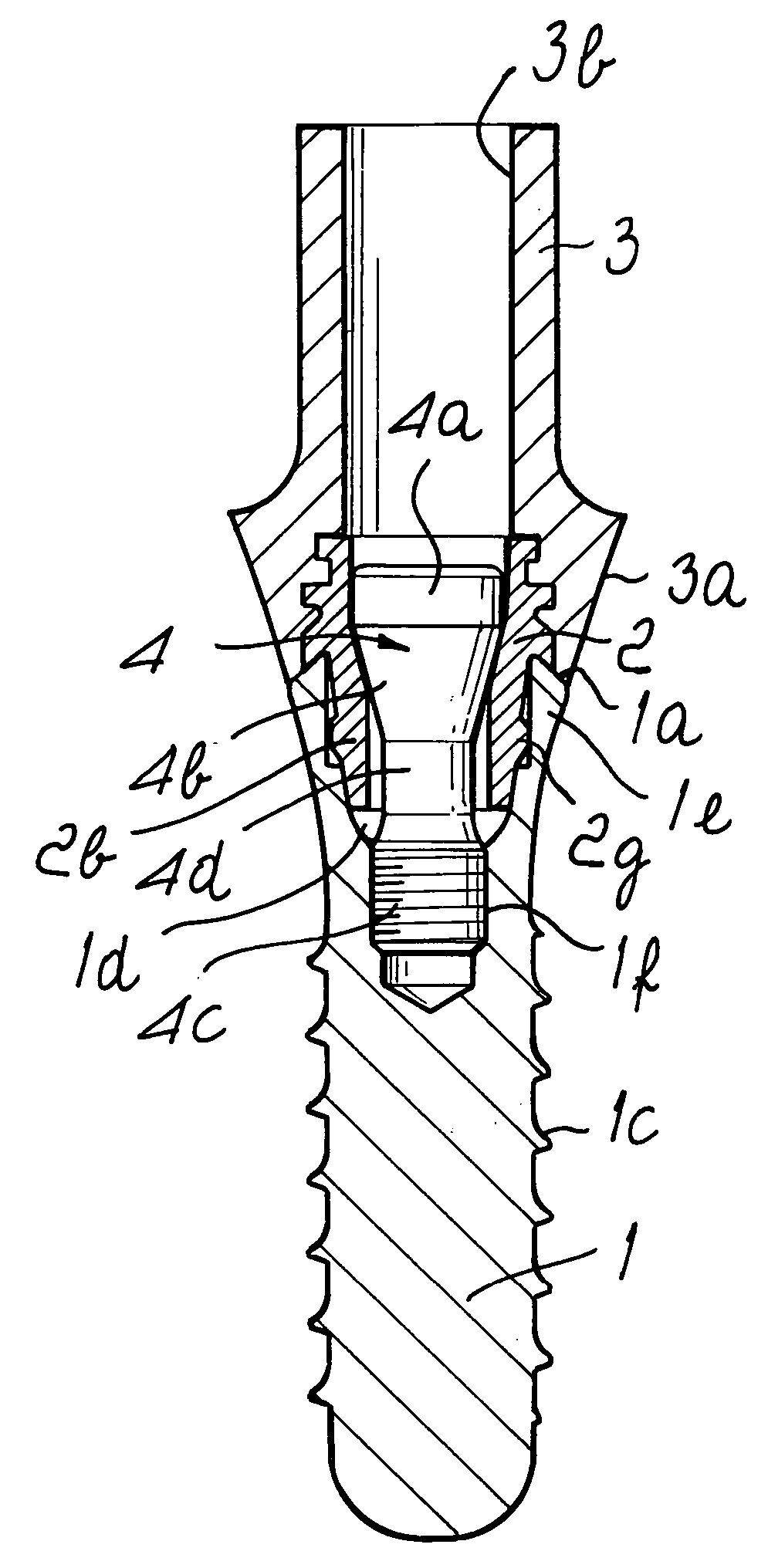
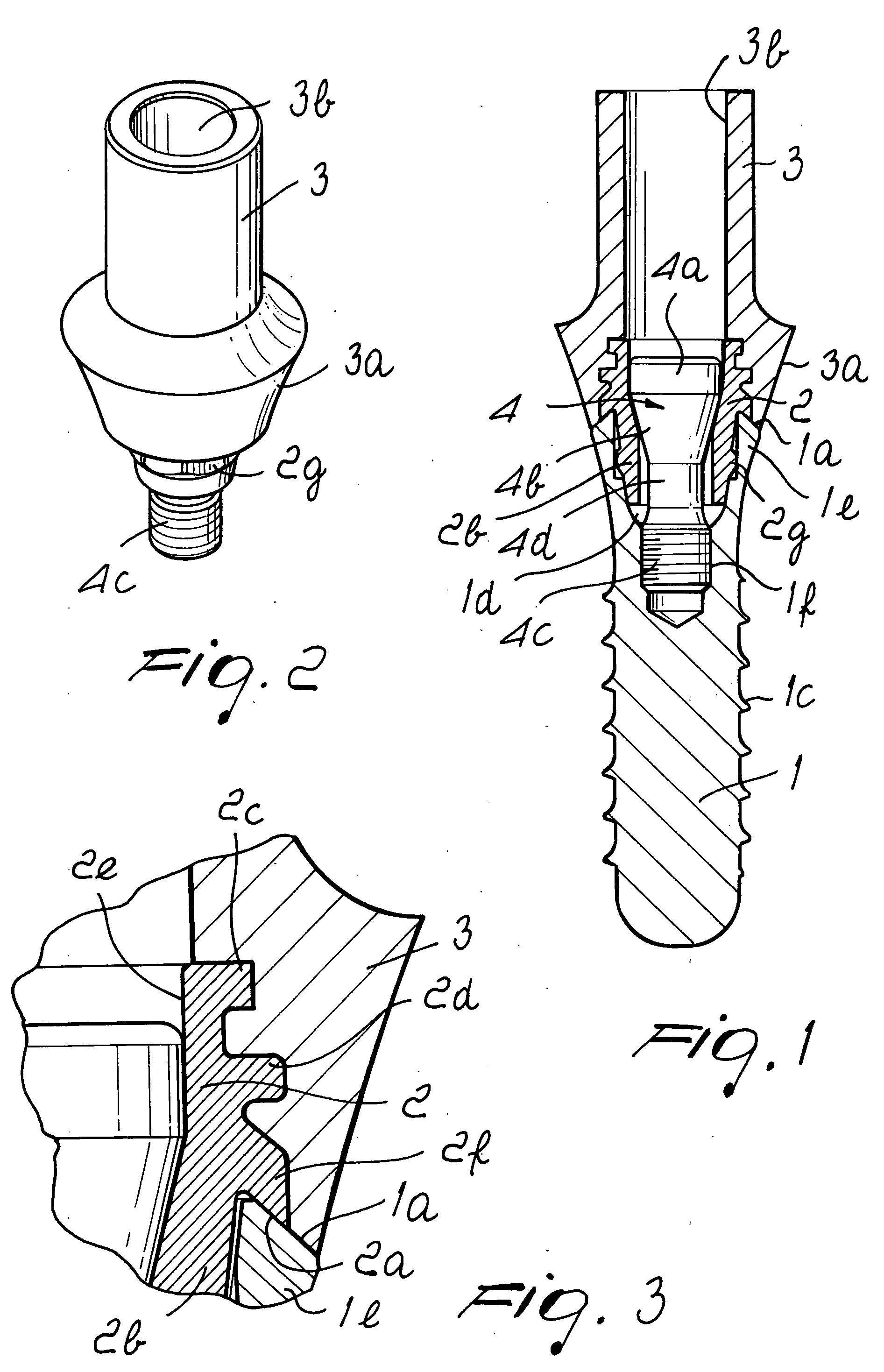
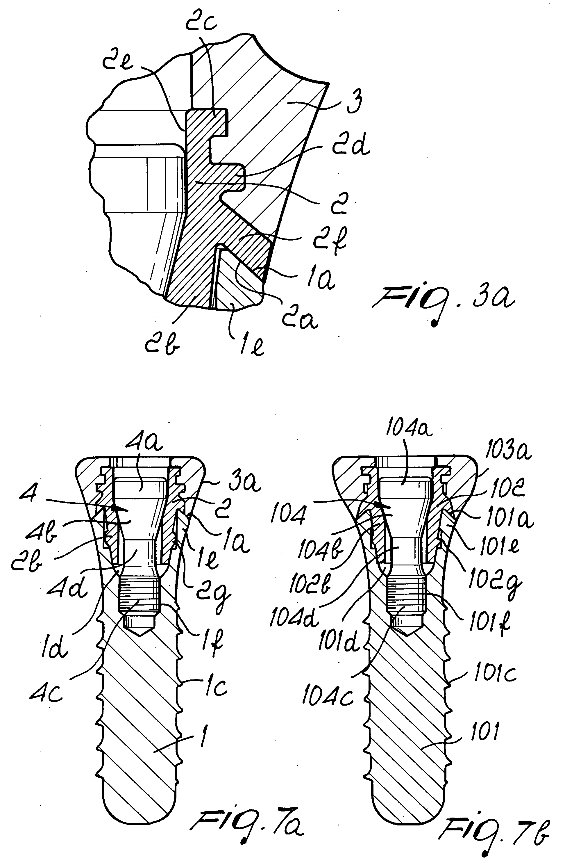
[0036]FIG. 3a is a variation of FIG. 1 where the inlay 2 is visible laterally in the assembled state of the implant system. This variation may be used in a biologically non-aggressive environment and provides for an even further improved force distribution as the contacting surface between the inlay and the dental implant is maximized. Otherwise all details of FIG. 3a are identical to FIG. 1 and will therefore be omitted.

[0037] Also FIG. 7a is a variation of the first embodiment of FIG. 1 implemented as a healing abutment. Otherwise, again, all details of FIG. 7a are identical to FIG. 1 and will therefore be omitted. The healing abutment may be manufactured to be smaller sized as shown in FIG. 7a or may be processed in situ by the dental technician or dental surgeon from a larger sized abutment to a smaller size.

second embodiment

[0038] FIGS. 4 to 6 show the implant system according to the present invention, wherein generally the single parts are corresponding to those of FIGS. 1 to 3 and therefore the detailed description thereof has been omitted. It is noted that the reference numerals are augmented by 100 as compared to FIGS. 1 to 3.

[0039] Varying from FIGS. 1 to 3, FIG. 6 shows that the inlay 102 could have different profiles in order to improve the stability of the interfaces inlay-abutment and inlay-dental implant. In particular, in this second embodiment, the inlay 102 has a downward-facing shoulder 102f, which entirely overlaps the upper surface 101a of the neck portion 101e of the implant 101. The cross-sectional view of FIG. 6 shows the tapered shape of the shoulder 102f.

[0040] As above mentioned, the presence of the integral inlay 102 interposed between the abutment 103 and the dental implant 101 enforces the whole construction of the implant system and serves for a better force distribution as w...


PUM


Abstract

Abutment for dental implant systems of the kind suitable to be associated to a dental implant, wherein the abutment comprises an inlay, and wherein the inlay is provided at its upper part with an external profile comprising means for connecting and permanently jointing the inlay to the abutment. Further, the inlay may be shaped such that it is completely surrounded by the abutment in the assembled state of the dental implant system.

Description

[0001] The present invention relates in general to an abutment for a dental implant system and in particular to a healing or a temporary abutment for a dental implant system. [0002] As known to those expert in the field, in the reconstruction of missing or lost teeth, a dental implant is inserted in and secured to the patient's jawbone. [0003] After a dental replacement by means of such an artificial dental implant has occurred, a healing period has to be observed in order to allow a correct osseo-integration of the dental implant in the bone tissue. Further, a sufficient healing time span must be provided for the surgical wound of the bone and the gingival tissues. In order to allow the completion of the healing process, a provisional head member, commonly called abutment, is mounted on the dental implant. Generally, abutments may be of healing type, so that only a healing function is provided without transmitting a load to the portion underlying the abutment, or of the temporary (...

Claims


Application Information

Patent Timeline
Patent Type & Authority Applications(United States)
IPC IPC(8): A61C8/00
CPCA61C8/005A61C8/0054A61C8/0069A61C8/008
Inventor LINDER, ANDREASGUNTER, DANIELHEYDEN, MELANIE
Owner STRAUMANN HLDG AG
Why Eureka
Try Eureka