Storage apparatus

a technology for storage apparatuses and storage devices, applied in the field of storage apparatuses, can solve problems such as data loss

Inactive Publication Date: 2006-05-18
HITACHI LTD
View PDF4 Cites 7 Cited by
  • Summary
  • Abstract
  • Description
  • Claims
  • Application Information

AI Technical Summary

Benefits of technology

[0007] Hence, an object of the present invention is to provide a storage apparatus, which can avoid the data lost even whe

Problems solved by technology

However, in the case of a technique disclosed in Japanese Patent Laid-open No. 7-160380, there has been the following problem.
In this case, when the short-circuit fault occurs in the power source line of one har

Method used


Image

  • Storage apparatus
  • Storage apparatus
  • Storage apparatus

Examples


first embodiment

[0036]

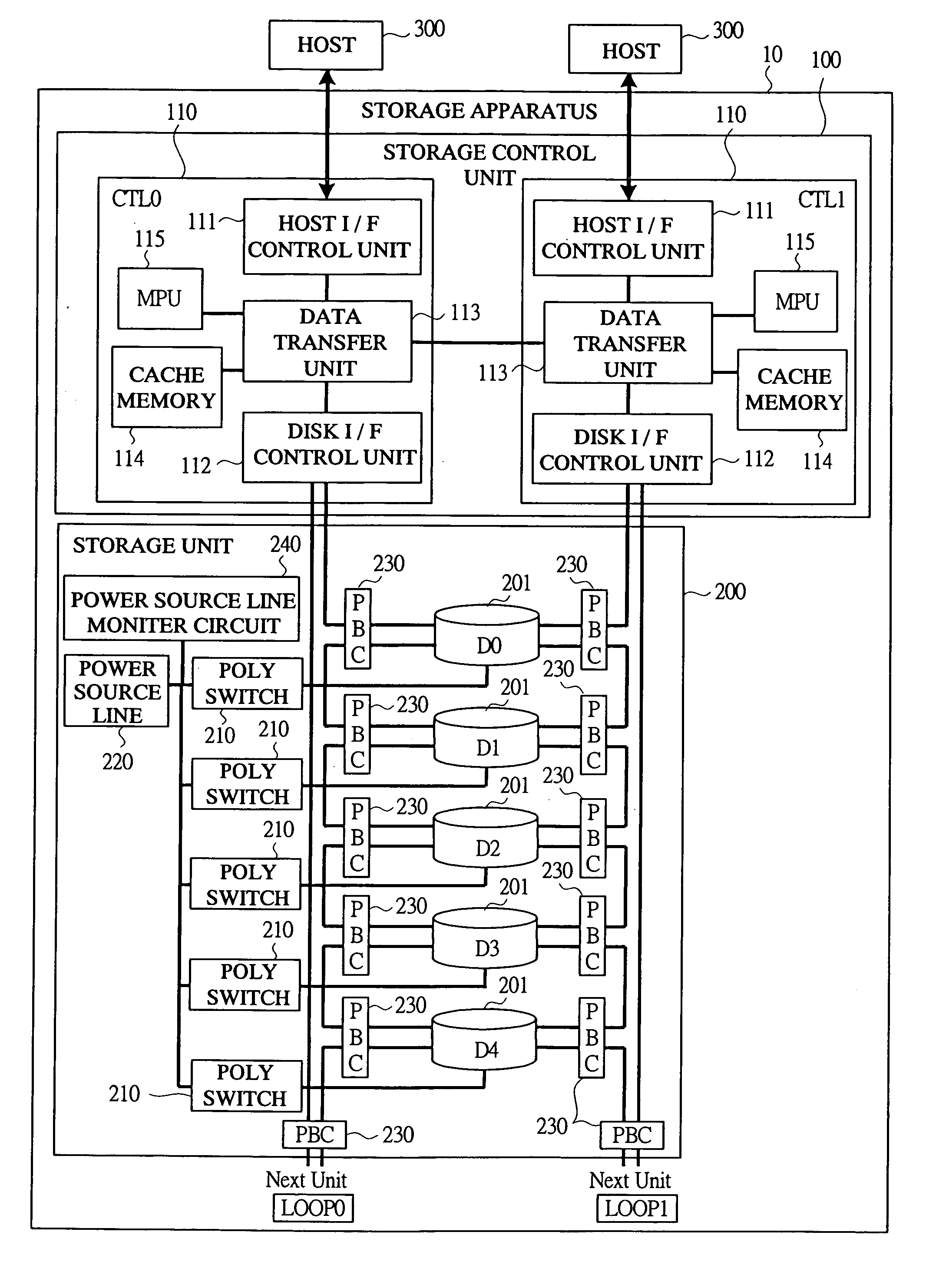
[0037] A configuration of a storage apparatus according to a first embodiment of the present invention will be described with reference to FIG. 1. FIG. 1 is a block diagram showing the configuration of the storage apparatus according to the first embodiment of the present invention.

[0038] In FIG. 1, a storage apparatus 10 is composed of a storage control unit 100 and a storage unit 200.

[0039] The storage control unit 100 comprises storage controller boards (CTL0 and CTL1) 110 including a host interface control unit 111, a disk interface control unit 112, a data transfer unit 113, a cache memory 114, and a central processing unit (MPU) 115.

[0040] The host interface control unit 111 comprises a communication interface for performing a communication with a host (host device) 300, and controls the data reception from the host 300 and the data transmission to the host 300.

[0041] The disk interface control unit 112 comprises the communication interface for performing the communi...

second embodiment

[0078] In the first embodiment, the description has been made by using an example of the hard disk drive 201 of the fiber channel drive connected by the fiber channel. However, even in a SATA drive connected by a serial ATA (SATA), the operation at the time of the short-circuit fault of the power source line can be performed in the same manner.

[0079]

[0080] A configuration in which a SATA drive of a storage apparatus is connected according to a second embodiment of the present invention will be described with reference to FIG. 12. FIG. 12 is a block diagram showing the configuration to which the SATA drive is connected in the storage apparatus according to the second embodiment of the present invention.

[0081] In FIG. 12, in the case of a hard disk drive 250 of the SATA drive, since the connection is made on a one for one basis, a number of lines corresponding to that of the hard disk drives 250 comes from the disk interface control unit 112 to the hard disk drives 250.

[0082] Since...

third embodiment

[0089] Different from the first embodiment in which the cutting off of a fiber line is performed by the detection of a voltage abnormality by a power source line monitor circuit 240, when the abnormality of a hard disk drive 201 due to the short circuit and the like in the power source line thereof is detected on a storage control unit 100 side, an access from the host 300 is made to wait until a certain period of time passes in the third embodiment.

[0090] The configuration of a storage apparatus 10 of the third embodiment is the same as that of the first embodiment except that a power source line monitor circuit 240 is not connected to a power source line 220.

[0091] Next, the operation at the time of short circuit of the power source line in the storage apparatus according to the third embodiment of the present invention will be described with reference to FIGS. 13 and 14. FIG. 13 is a flowchart showing the operation at the time of short circuit of the power source line in the st...


PUM


Abstract

This invention provides a storage apparatus which can avoid a data lost even when a short-circuit fault occurs in a power source line which is not made redundant for a plurality of hard disk drives. In the storage apparatus, a storage control unit comprises a host interface control unit, a disk interface control unit, a cache memory, and a data transfer unit, and a storage unit includes poly switches provided for each of the power source lines to a plurality of hard disk drives and a power source line monitor circuit for monitoring the voltage of the power source line. When the voltage abnormality due to a voltage drop of the power source line is detected by the power source line monitor circuit, a data line connecting the disk interface control unit and the plurality of hard disk drives is cut off.

Description

CROSS-REFERENCE TO RELATED APPLICATION [0001] The present application claims priority from Japanese patent application No. JP 2004-320102 filed on Nov. 4, 2004, the content of which is hereby incorporated by reference into this application. BACKGROUND OF THE INVENTION [0002] The present invention relates to a storage apparatus and, in particular, to a technique effectively applied to a data lost avoidance when a fault occurs in a power source line of a hard disk drive. [0003] Heretofore, there has been a technique which enables a hot swap of each package in the apparatus in order to achieve a non-stop operation of the apparatus when the fault of the storage apparatus has occurred, and which does not exert any influence on an operation of the apparatus at the time of the hot swap of each package (See, for example, Japanese Patent Laid-open No. 7-160380). [0004] Further, in recent years, the amount of data stored in the storage apparatus has become increasingly large. With the increas...

Claims


Application Information

Patent Timeline
IPC IPC(8): G06F11/00
CPCG11B19/047
Inventor YAGI, SATOSHI
Owner HITACHI LTD
Why Eureka
Try Eureka