Embroidery frame

a frame and embroidery technology, applied in the field of embroidery frames, can solve the problem that the outer frame does not allow the upward transformation of the inner frame, and achieve the effect of preventing upward bending deformation

Active Publication Date: 2006-05-25
BROTHER KOGYO KK
View PDF10 Cites 1 Cited by
  • Summary
  • Abstract
  • Description
  • Claims
  • Application Information

AI Technical Summary

Benefits of technology

[0010] Therefore the object of the present disclosure is to provide an embroidery frame that prevents the upward-bending deformation which is caused by the tension of the workpiece cloth.
[0012] According to the above-described construction, when the cloth to be embroidered is clamped between the outer and inner frames, the first inclined surface of the outer frame contacts the second inclined surface of the inner frame from the obliquely upward direction. Therefore, even if a force to transform the inner frame in the upward direction is operated on the inner frame by the cloth tension, the outer frame does not allow the upward transformation of the inner frame, and the cloth can be securely clamped between the outer frame and the inner frame. Also, since the embroidery area portion of the cloth can be retained as a flat surface, the quality of the embroidery pattern formed on the embroidery area portion can be improved.

Problems solved by technology

Therefore, even if a force to transform the inner frame in the upward direction is operated on the inner frame by the cloth tension, the outer frame does not allow the upward transformation of the inner frame, and the cloth can be securely clamped between the outer frame and the inner frame.

Method used


Image

  • Embroidery frame
  • Embroidery frame
  • Embroidery frame

Examples


first embodiment

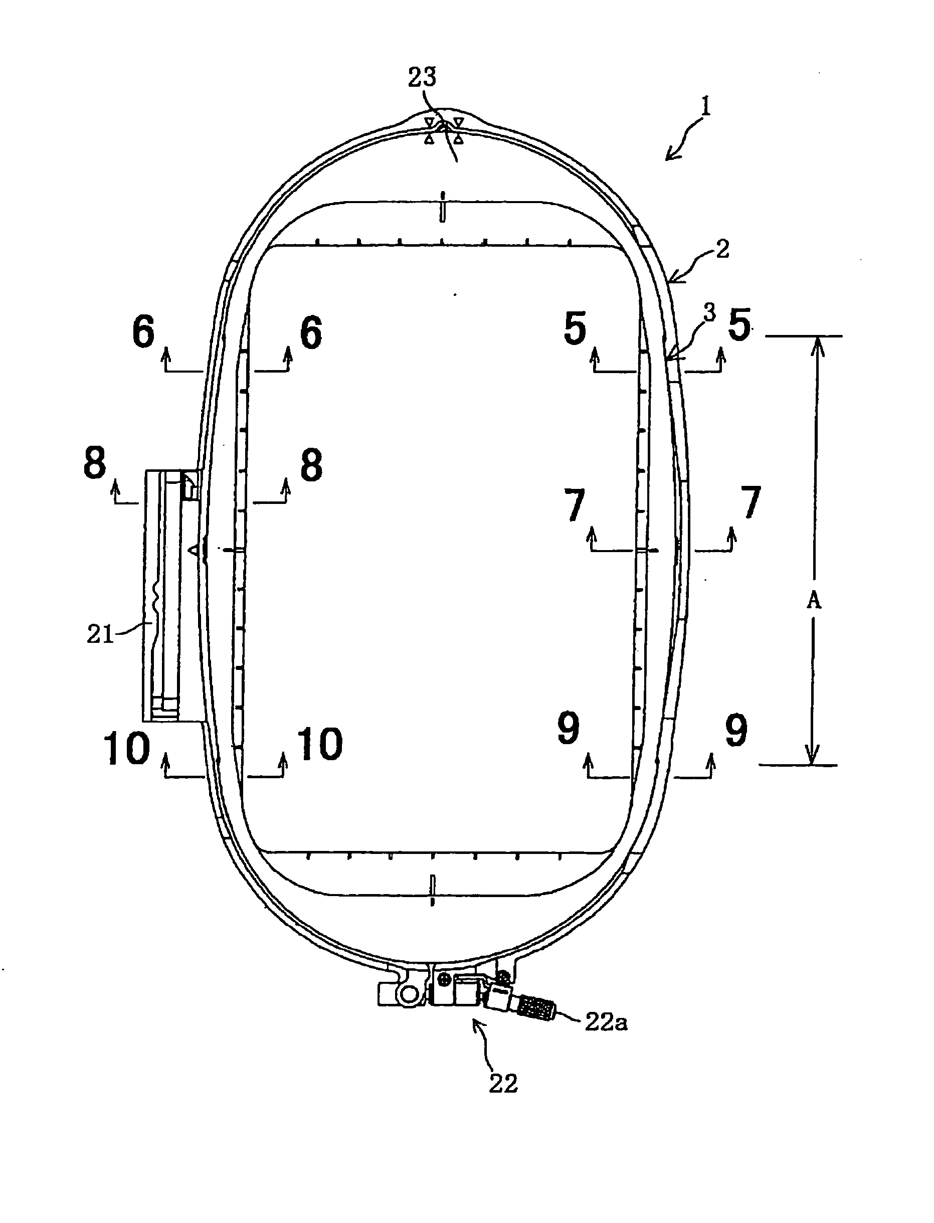
[0029] the present invention will be described with reference to FIGS. 1 to 10. In the embodiment, the invention is applied to an embroidery frame attached to an embroidery unit of a sewing machine capable of embroidery sewing. Referring to FIG. 1, an embroidery frame 1 according to the present invention is formed in an elongated substantially elliptic form or an oval form; and is constructed by an outer frame 2 and an inner frame 3, which is attached to the inner side of the outer frame 2 so as to clamp the workpiece cloth. Therefore, an inner peripheral surface of the outer frame 2 is defined as a cloth-clamping surface 2a and an outer peripheral surface of the inner frame 3 is defined as a cloth-clamping surface 3a.

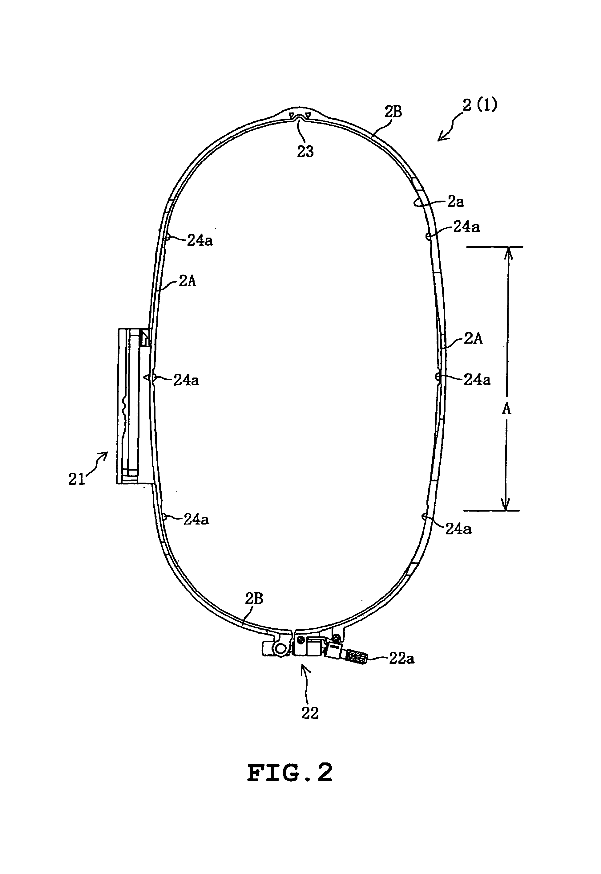
[0030] The outer frame 2 is formed by a synthetic resin, and as shown in FIG. 2, is constructed in an elongate substantially elliptic form having a pair of substantially straight portions 2A and a pair of circular-arc portions 2B. In FIG. 2, symbol A indicates a range...


PUM


Abstract

An embroidery frame is disclosed which is detachably attached to an embroidery unit and provided with outer and inner frames clamping embroidery cloth. The embroidery frame includes a first inclined surface which is provided at least on a part of a cloth-clamping surface of the outer frame that holds the cloth between the inner and outer frames, and which is upwardly inclined toward an inside of the outer frame. The embroidery frame further includes a second inclined surface which is provided in a portion of the cloth-clamping surface of the inner frame corresponding to the first inclined surface, the inner frame holding the cloth between the outer and inner frames, and which is upwardly inclined toward an inside of the inner frame.

Description

CROSS-REFERENCE TO RELATED APPLICATIONS [0001] This application is based upon and claims the benefit of priority from the prior Japanese Patent Application No. 2004-339344, filed on Nov. 24, 2004 the entire contents of which are incorporated herein by reference. BACKGROUND [0002] The present disclosure relates to an embroidery frame that holds a workpiece cloth to be sewn between an outer frame and an inner frame. TECHNICAL FIELD [0003] Conventional embroidery frames have generally been constructed by an outer frame and an inner frame. Tension is applied to workpiece cloth placed on the outer frame by pressing the inner frame into the outer frame. A fastening screw is provided on the outer frame, and the fastening screw is tightened so that the workpiece cloth is clamped between the outer and inner frames. [0004] The embroidery frame having the above construction is disclosed, for example, in JP-U-7-15793. The outer frame of the embroidery frame is provided with a scale correspondin...

Claims


Application Information

Patent Timeline
Patent Type & Authority Applications(United States)
IPC IPC(8): D05C9/04
CPCD05B39/00D05C9/04
Inventor FUKAO, HIROAKI
Owner BROTHER KOGYO KK
Why Eureka
Try Eureka