Apparatus and method for slicing an ingot

Active Publication Date: 2006-05-25
LG SILTRON
View PDF9 Cites 10 Cited by
  • Summary
  • Abstract
  • Description
  • Claims
  • Application Information

AI Technical Summary

Benefits of technology

[0012] The disclosed embodiments relate to a method and an apparatus for slicing an

Problems solved by technology

Accordingly, at the beginning of slicing, it is difficult for the wire to be positioned at a desired position of the ingot.
As a result, the sliced wafer may have undesirably high nanotopography at one or more surface portions thereof, even after successively having achieved the lapping process, the etching process, and the polishing processes.
High nanotopography generally causes

Method used


Image

  • Apparatus and method for slicing an ingot
  • Apparatus and method for slicing an ingot
  • Apparatus and method for slicing an ingot

Examples


Embodiment Construction

[0034] Exemplary embodiments of the present invention will hereinafter be described in detail with reference to the accompanying drawings.

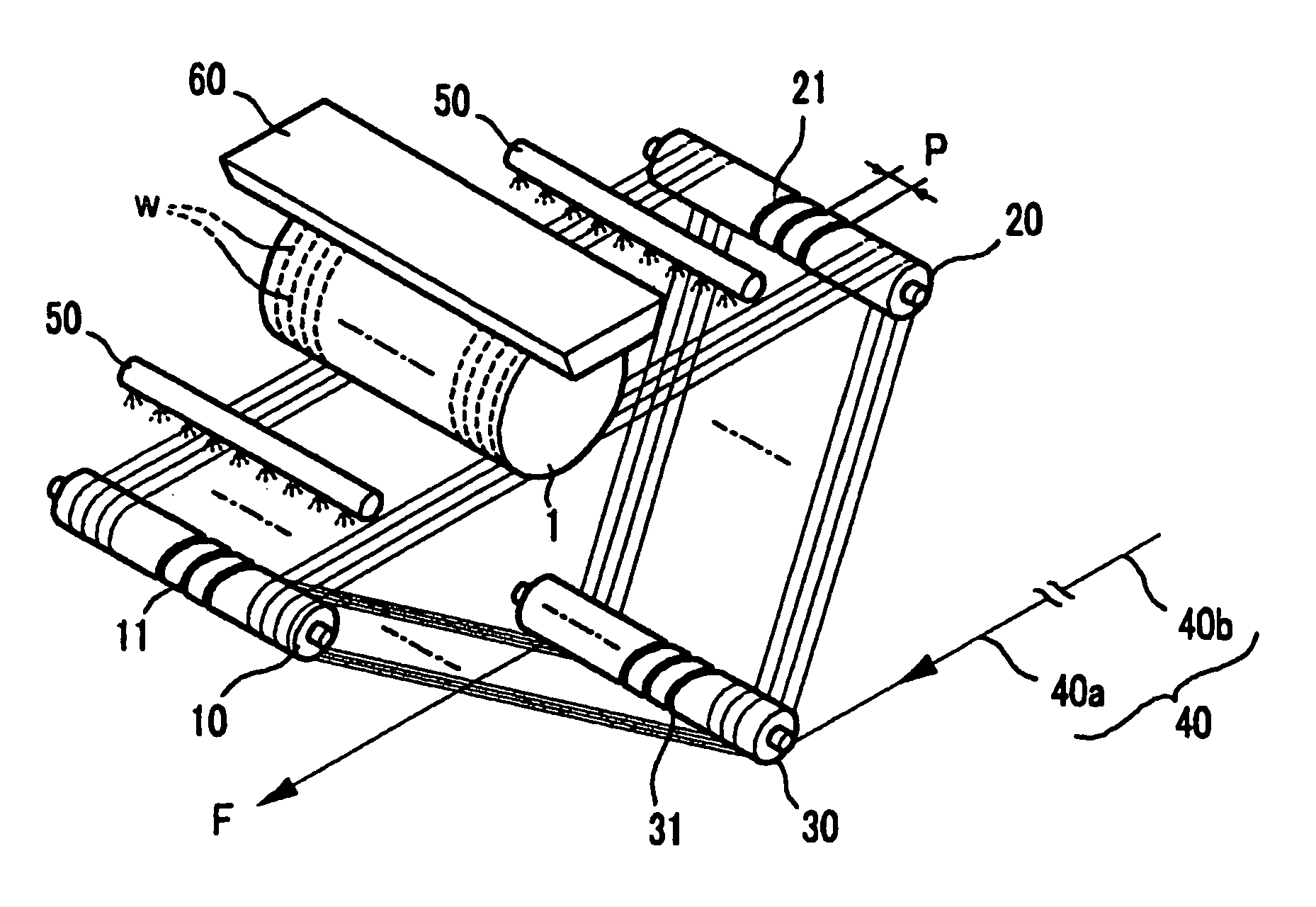
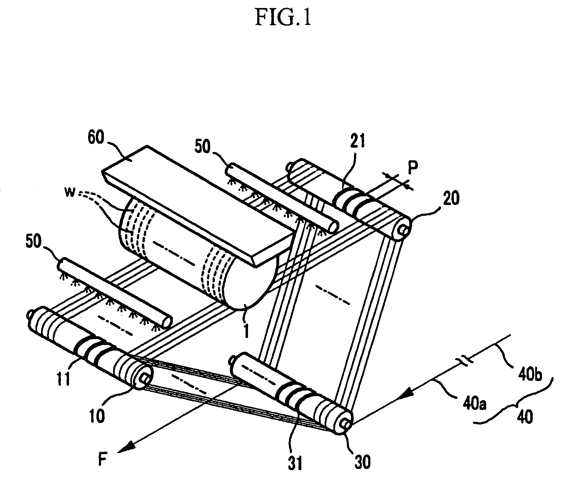
[0035]FIG. 1 is a perspective view of an apparatus for slicing an ingot according to a first exemplary embodiment of the present invention.

[0036] Referring to FIG. 1, an apparatus for slicing an ingot includes first, second, and third work rollers 10, 20, and 30, a wire 40, a slurry supplier 50, and a work plate 60.

[0037] In order to slice the ingot 1 into a plurality of wafers W, the first and second work rollers 10 and 20 are configured such that a wire 40 is repeatedly wound over these two rollers 10 and 20 and is supported in a tensioned state there between. In detail, the first and second work rollers 10 and 20 are located in parallel, and the first and second work rollers respectively have a plurality of grooves 11 and 21 engraved thereon with a uniform pitch P. To reduce the complexity of FIG.1 only a portion of the grooves 11 and 21 are...


PUM

PropertyMeasurementUnit
Temperatureaaaaaaaaaa
Fractionaaaaaaaaaa
Lengthaaaaaaaaaa

Abstract

A method for slicing an ingot may improve nanotopography at a surface of a wafer. In the method, an ingot is sliced into a plurality of wafers via a slurry while slurry is supplied to a moving wire. A first wire to form a first slicing portion at the wafer firstly slices one side of the ingot. A second wire secondly slices the remaining portion of the ingot to form a second slicing portion continued from the first slicing portion, wherein the first wire has a smaller diameter than that of the second wire.

Description

CROSS-REFERENCE TO RELATED APPLICATION [0001] This application claims priority to and the benefit of Korean Patent Application 10-2004-0096218 filed in the Korean Intellectual Property Office on Nov. 23, 2004, the disclosure of which is incorporated herein by reference. BACKGROUND [0002] 1. (a) Technical Field [0003] This application relates to an apparatus and a method for slicing an ingot. More particularly, the present invention relates to an apparatus and a method for slicing an ingot capable of improving fine unevenness of a wafer, i.e., its nanotopography. [0004] 2. (b) Description of the Related Art [0005] Generally, a wafer manufacturing process includes an ingot growing process, a slicing process, an edge grinding process, a lapping process, an etching process, a back side polishing process, a pre-anneal cleaning process, an edge polishing process, and a front polishing process. In the ingot growing process, silicon (Si) is induced from sand and is then purified to make a s...

Claims


Application Information

Patent Timeline
IPC IPC(8): B28D1/08
CPCB24B27/0633B28D5/0064B28D5/007B28D5/045Y10T83/9292Y02P70/10H01L21/304
Inventor JI, EUNSANGLEE, KYUNGMOO
Owner LG SILTRON
Why Eureka
Try Eureka