
Composite bushing having dual damping capability

a composite bushing and damping capability technology, applied in the direction of shock absorbers, machine supports, transportation and packaging, etc., can solve the problems of inability to derive the benefits of the bushing disclosed in the references, undesirable axial deflection of the bushing, and adverse effects of axial deflection on the bushing

Inactive Publication Date: 2006-05-25
HONDA MOTOR CO LTD
View PDF8 Cites 13 Cited by
  • Summary
  • Abstract
  • Description
  • Claims
  • Application Information

AI Technical Summary

Benefits of technology

[0015] In accordance with an illustrative embodiment of the present invention, a composite bushing is provided having an elastomeric annulus which is radially sectioned, to provide plural wedge-shaped elastic members. Selected individual elastic members have a specific resiliency which varies from other elastic members. The wedge-shaped members cooperate to provide an annulus having circumferentially varying resiliency. As a result, the inventive bushing provides a variable resistance to deflection, which depends upon the direction of the applied load.
[0016] More specifically, illustrative embodiment of the present invention provides a radially sectioned bushing in which the resiliency in a first radial direction differs significantly from the resiliency in a second radial direction, where the second radial direction is at an angle to the first radial direction. The resulting bushing configuration, when used to attenuate vibration and transmitted noise in an automotive assembly, provides improved vehicle handling and ride comfort.

Problems solved by technology

However, deflection of the bushing in the axial direction is undesirable, because such deflection causes axial spreading and consequent misalignment of the suspension system components.
Axial deflection also has adverse effects upon the bushing, since it tends to weaken the mechanical bond between the compressed elastomeric member and the respective inner and outer sleeves.
Hence, the bushings disclosed in the references are unable to derive the benefits from the attributes of one particular layer having a specific resiliency, because of the interdependence with the other radially disposed layer(s) having a different resiliency.
Controlling the resulting damping effect can be difficult.

Method used


Image

  • Composite bushing having dual damping capability
  • Composite bushing having dual damping capability
  • Composite bushing having dual damping capability

Examples


Embodiment Construction

[0028] A number of selected illustrative embodiments of the present invention will be described, with reference to the drawings.

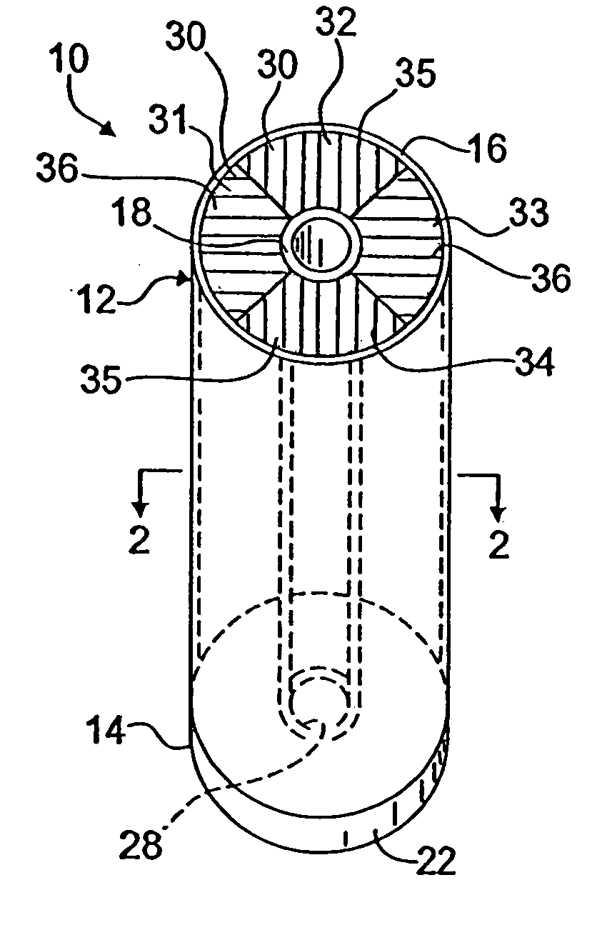
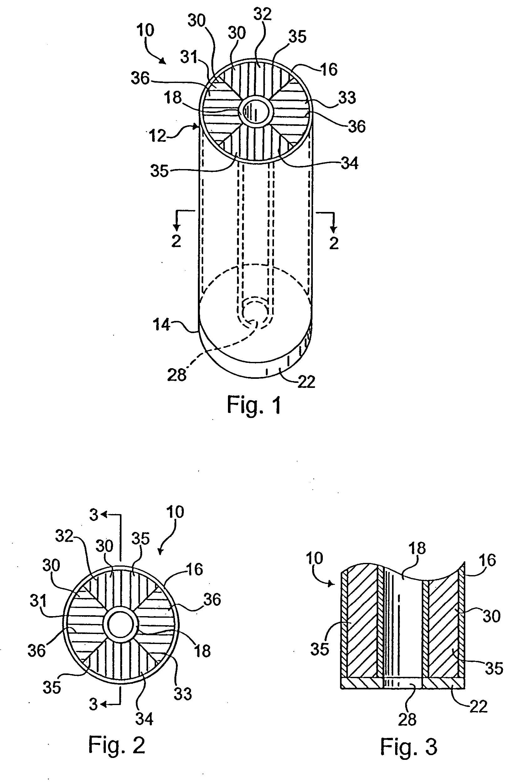
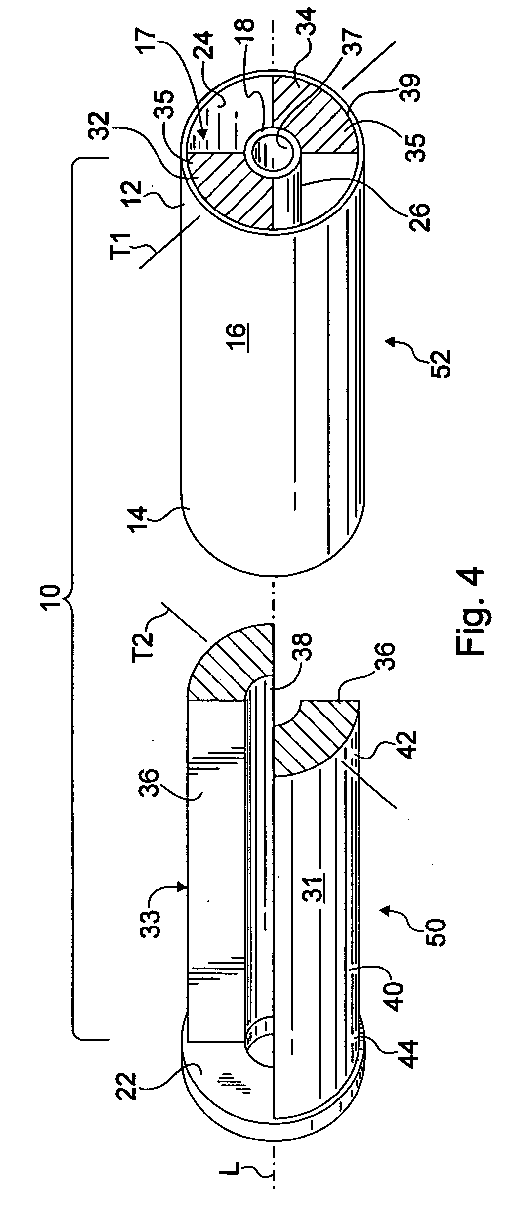
[0029] In each of FIGS. 1 through 4, according to instant invention; there is shown an embodiment of a radially segmented composite elastomeric bushing 10 characterized by directionally dependent resistances to deflection. Further embodiments are illustrated in FIGS. 5 and 6.

[0030] More specifically, in the first illustrative embodiment of FIGS. 1-4, the present invention provides a composite bushing 10, in which the spring rate, or resistance to deflection in a first radial direction appreciably differs from the spring rate or resistance to deflection in a second radial direction that is at an angle to the first radial direction, to improve vehicle handling and ride comfort.

[0031] The inventive composite bushing 10 includes a rigid, axially elongated hollow cylindrical outer sleeve 16, and a rigid, axially elongated hollow cylindrical inner sleeve 18 di...


PUM


Abstract

A composite bushing including an outer sleeve coaxially surrounding an inner sleeve, and including an elastomeric body extending between the outer sleeve and the inner sleeve. The elastomeric body is provided with circumferentially alternating wedge sections having different physical characteristics, so as to provide a bushing having directional differences in resistance to deflection. The resiliency in a first radial direction appreciably differs from the resiliency in a second radial direction, where the second radial direction is at an angle to the first radial direction. The resulting bushing configuration can be used to attenuate vibration and noise in a vehicle, and thereby contribute to improved vehicle handling and ride comfort.

Description

BACKGROUND OF THE INVENTION [0001] 1. Field of the Invention [0002] The present invention relates to bushings, which are extensively used in a variety of assemblies within automobiles, particularly in suspension systems. More specifically, the present invention relates to a sectioned composite bushing having directionally variable dampening properties. In addition, the inventive bushing is characterized by inner and outer cylindrical collars bridged by circumferentially arranged elastomeric sections. The inventive bushing attenuates vibration and noise transmitted through metal structures. [0003] 2. Description of the Background Art [0004] In today's automotive industry, extensive time and effort has been expended to reduce vibration, and vibration and friction-induced noise in vehicles, while improving ride comfort and vehicle handling. Technologically refined vibration isolators and resilient bushings have been developed to achieve better vibration isolation and noise control, and...

Claims


Application Information

Patent Timeline
Patent Type & Authority Applications(United States)
IPC IPC(8): F16M7/00
CPCB60G7/02B60G2204/143B60G2204/4104B60G2800/162F16F3/0935
Inventor HEES, ERICH
Owner HONDA MOTOR CO LTD
Learn More