Method and apparatus for monitoring optical fibers of passive optical network system

US20060110161A1Inactive Publication Date: 2006-05-25ELECTRONICS & TELECOMM RES INST

Image

  • Method and apparatus for monitoring optical fibers of passive optical network system
  • Method and apparatus for monitoring optical fibers of passive optical network system
  • Method and apparatus for monitoring optical fibers of passive optical network system

Examples


Embodiment Construction

[0027] The present invention will now be described more fully with reference to the accompanying drawings, in which exemplary embodiments of the invention are shown. The invention may, however, be embodied in many different forms and should not be construed as being limited to the embodiments set forth herein; rather, these embodiments are provided so that this disclosure will be thorough and complete, and will fully convey the concept of the invention to those skilled in the art. Throughout the drawings, like reference numerals refer to like elements.

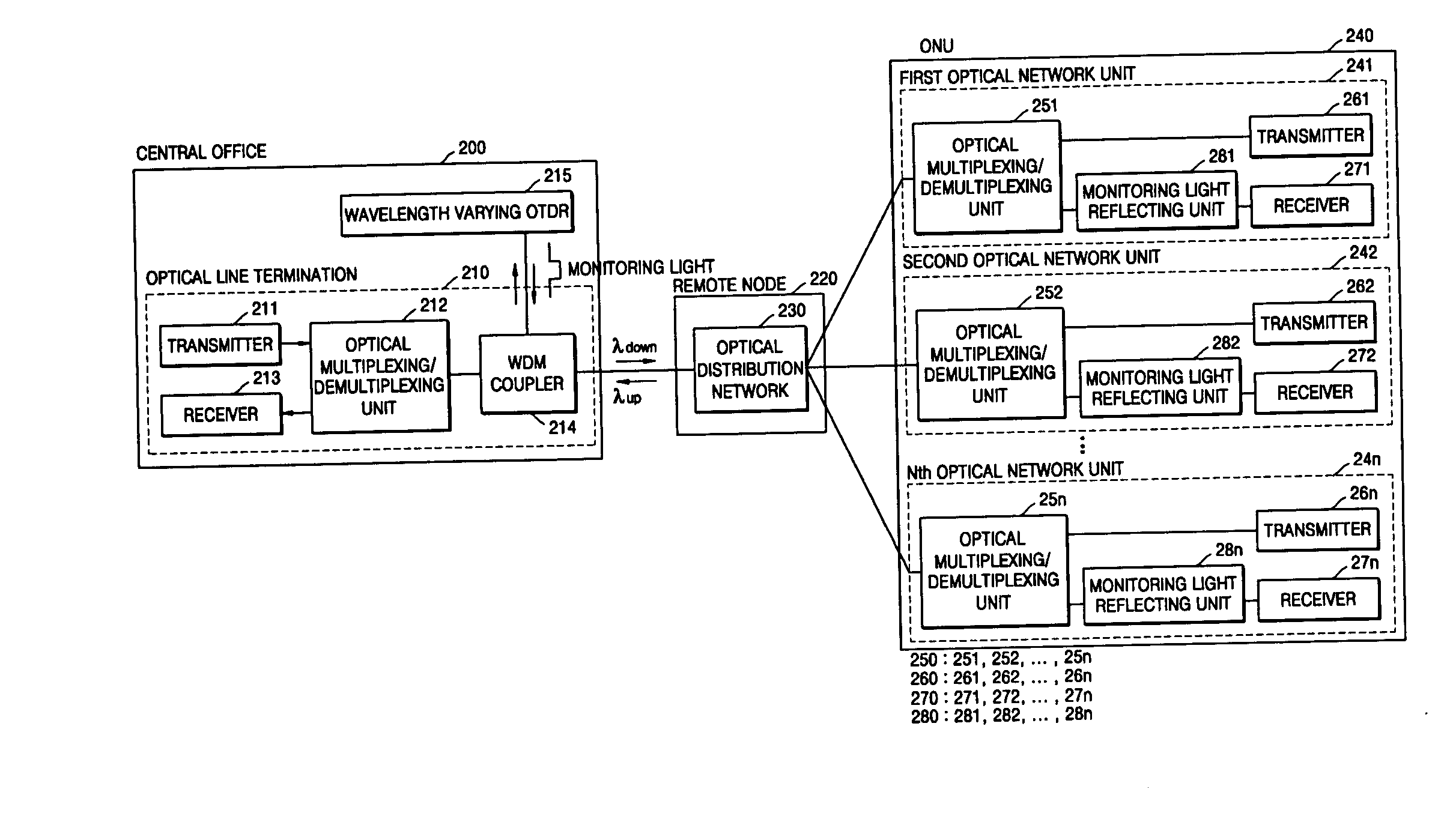
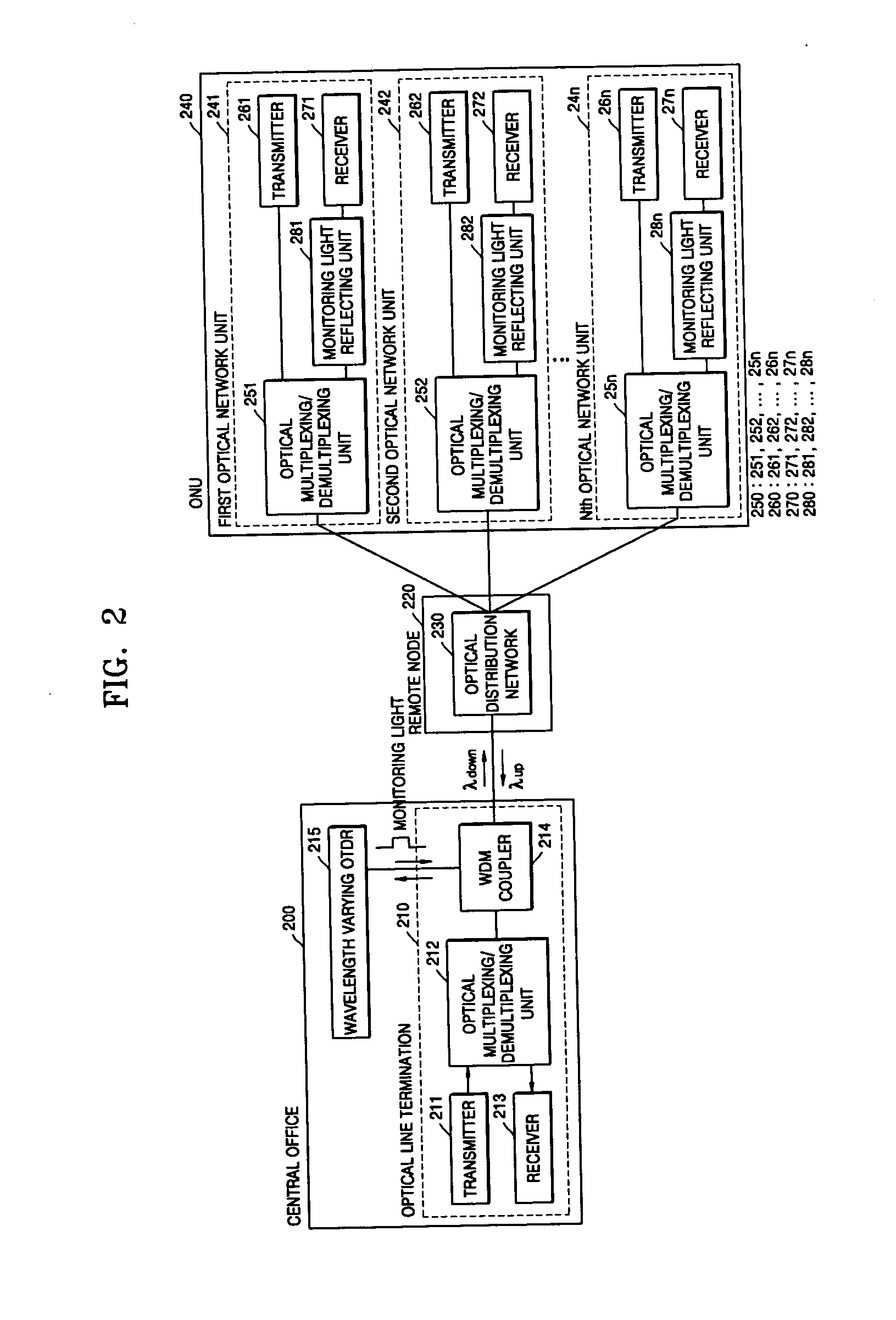
[0028]FIG. 2 is a block diagram of a passive optical network system including an optical fiber monitoring device according to an embodiment of the present invention. Referring to FIG. 2, the passive optical network of the present invention includes an optical line termination 210 located in a central office 200, an optical distribution network 230 of a remote node 220 that is a local office, and an optical network unit 240 on a subscr...


PUM


Abstract

Provided are an apparatus and method for monitoring optical fibers of a passive optical network system including an optical line termination located in a central office, a remote node that is a local office, and optical network units on the subscriber side. The apparatus respectively allocates monitoring light wavelengths to optical network units such that optical fibers of the respective optical network units can be identified and monitored using the monitoring light wavelengths, combines a monitoring light having various wavelengths and a downward optical signal using the WDM coupler, and analyzes signal waveforms of the monitoring light having various wavelengths reflected from the optical network units, to detect the position of a defect generated on an optical line. Accordingly, it is possible to transmit optical signals and monitor the physical states of the optical fibers of the optical network units.

Description

BACKGROUND OF THE INVENTION [0001] This application claims the priority of Korean Patent Application No. 10-2004-0095540 filed on Nov. 20, 2004, in the Korean Intellectual Property Office, the disclosure of which is incorporated herein in its entirety by reference. [0002] 1. Field of the Invention [0003] The present invention relates to a method and apparatus for monitoring optical fibers of a passive optical network system, and more particularly, to a method and apparatus for monitoring optical fibers of a passive optical network system, in which monitors light wavelengths are respectively allocated to optical network units such that a central office can identify and monitor the optical fibers of the optical network units, the central office combines a monitoring light having various wavelengths and a downward optical signal using a WDM coupler and inputs the combined signals to the optical network units, and the signal waveform of monitoring light having different wavelengths, ref...

Claims


Application Information

Patent Timeline
25 May 2006
Publication
US20060110161A1
IPC
H04J14/00
CPC
H04B10/071; H04B10/27; H04J14/0226; H04J14/0282; H04J14/0246; H04J14/0247; H04J14/025; H04J14/0252
Inventors
CHO, YUN HEE; KIM, KWANGJOON