

Protein detecting device
- Summary
- Abstract
- Description
- Claims
- Application Information
AI Technical Summary
Benefits of technology
Problems solved by technology
Method used
Image

Examples
Embodiment Construction
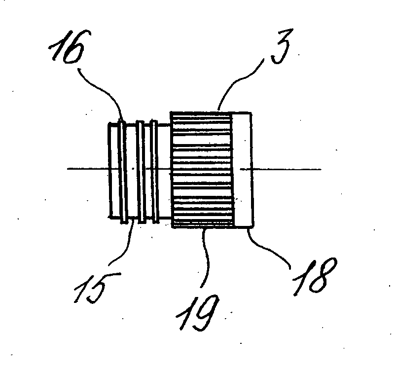
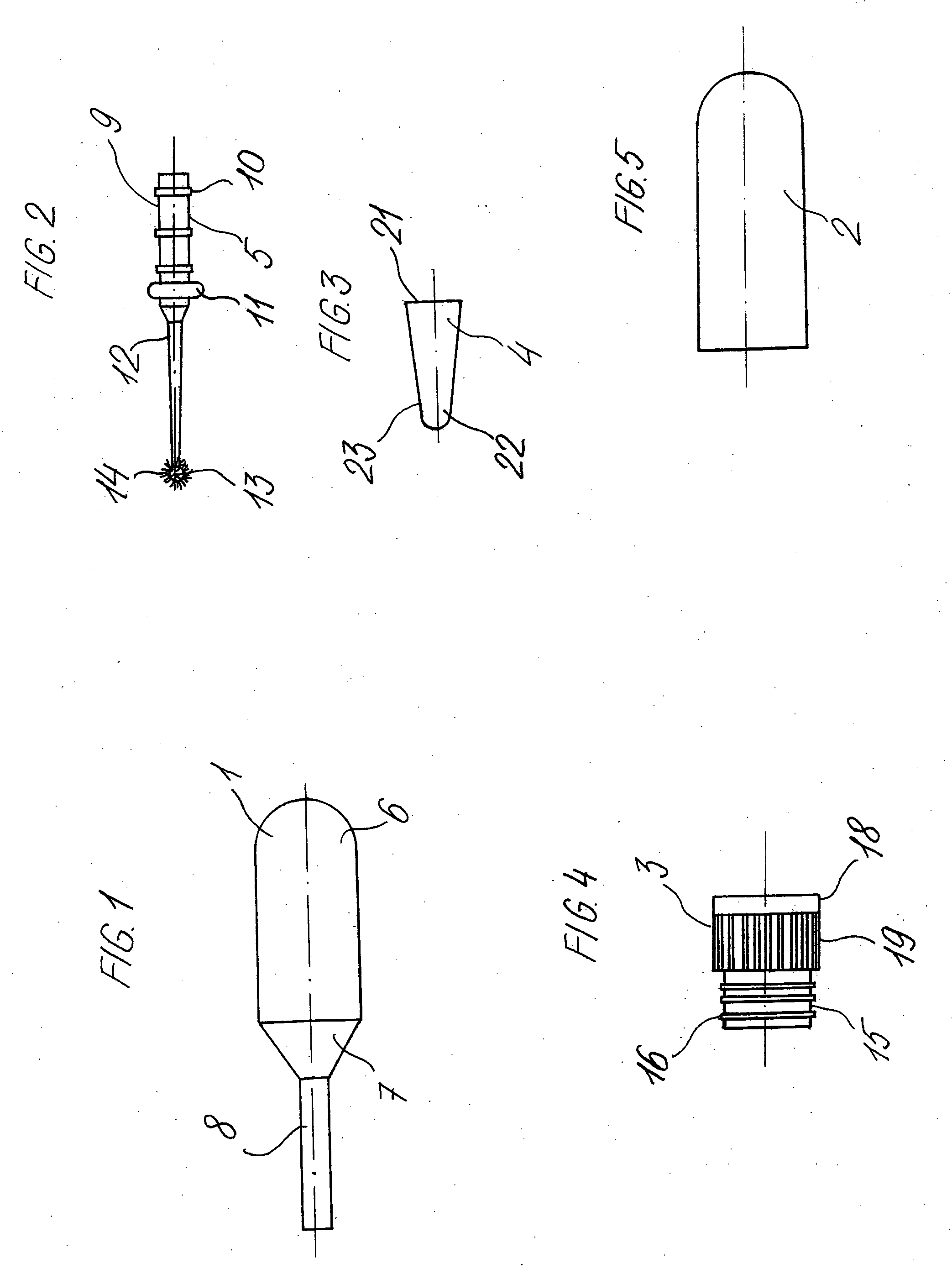
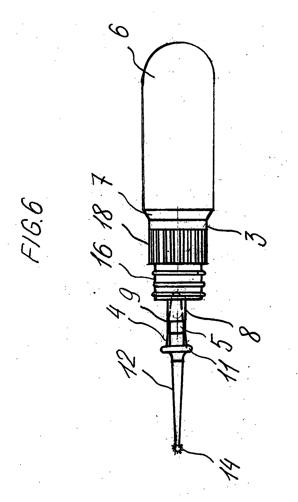
[0024] The preferred embodiment of the invention may have a reagent reservoir 1, a separate reaction chamber 2, a cap 3, a cone-shaped gasket 4, and an end member 5.
[0025] A reagent reservoir 1 may be a vessel for receiving a reagent that is used to test a substance. The reagent reservoir may be any suitable shape depending on the amount of a substance that is to be tested. As noted above, the reservoir is preferably made from a clear or transparent material so that the amount of reagent remaining can be ascertained. Alternatively, if desired only a portion of the reagent reservoir may be clear or transparent only so much of the reagent vessel would be clear give the user an idea of the amount of the reagent remaining. A suitable example of a reservoir is a pipette and the reservoir may have a squeezable portion 6, a neck portion 7 and a tubular portion 8. The tubular portion 8 may receive a cone-shaped gasket 4 which in turn may receive an end member 5.
[0026] In the preferred emb...
PUM
 Abstract
Description
Claims
Application Information