Valve designs for left ventricular conduits

a technology of valves and conduits, applied in the field of valve designs for left ventricular conduits, can solve the problems of coronary artery disease, heart attack, arrhythmia, and efficiency of heart pumping action, and achieve the effect of preventing the backflow of blood

Inactive Publication Date: 2006-05-25
WILK PATENT DEVMENT +1
View PDF5 Cites 96 Cited by
  • Summary
  • Abstract
  • Description
  • Claims
  • Application Information

AI Technical Summary

Benefits of technology

[0008] The preferred embodiments of the present invention address the need in the previous technology by providing a bypass system that avoids the stemotomy and other intrusive procedures normally associated with coronary bypass surgery. These embodiments also free the surgeon from the need to perform multiple anastomoses as is necessary in the current process.
[0009] The preferred device provides a conduit or shunt for diverting blood directly from the left ventricle of the heart to a coronary artery, at a point distal to the blockage or stenosis, thereby bypassing the blocked portion of the vessel. The conduit preferably comprises a tube adapted to be positioned in the myocardium and having a one way valve therein. The valve prevents the backflow of blood from the coronary artery into the left ventricle.
[0011] To prevent the backflow of blood from the coronary artery to the left ventricle of the heart, the conduit is provided with a one-way valve. The valve is preferably a windsock type valve, a flapper valve, a bi- or tricuspid valve, a ball valve, a valve formed from the myocardium itself, or a valve that opens and closes in response to the contraction and relaxation of the heart muscle, or in response to the electrical signals in the heart.

Problems solved by technology

Coronary artery disease is a major problem in the U.S. and throughout the world.
Coronary arteries as well as other blood vessels frequently become clogged with plaque, which at the very least impairs the efficiency of the heart's pumping action, and can lead to heart attack, arrhythmias, and death.
In more difficult cases, a bypass of the blocked vessel is necessary.
Such coronary artery bypass surgery, however, is a very intrusive procedure that is expensive, time-consuming and traumatic to the patient.
Furthermore, many patients are poor surgical candidates due to other concomitant illnesses.
However, such vascular treatments are not always indicated due to the type of location of the blockage or stenosis, or due to the risk of emboli.

Method used


Image

  • Valve designs for left ventricular conduits
  • Valve designs for left ventricular conduits
  • Valve designs for left ventricular conduits

Examples


Embodiment Construction

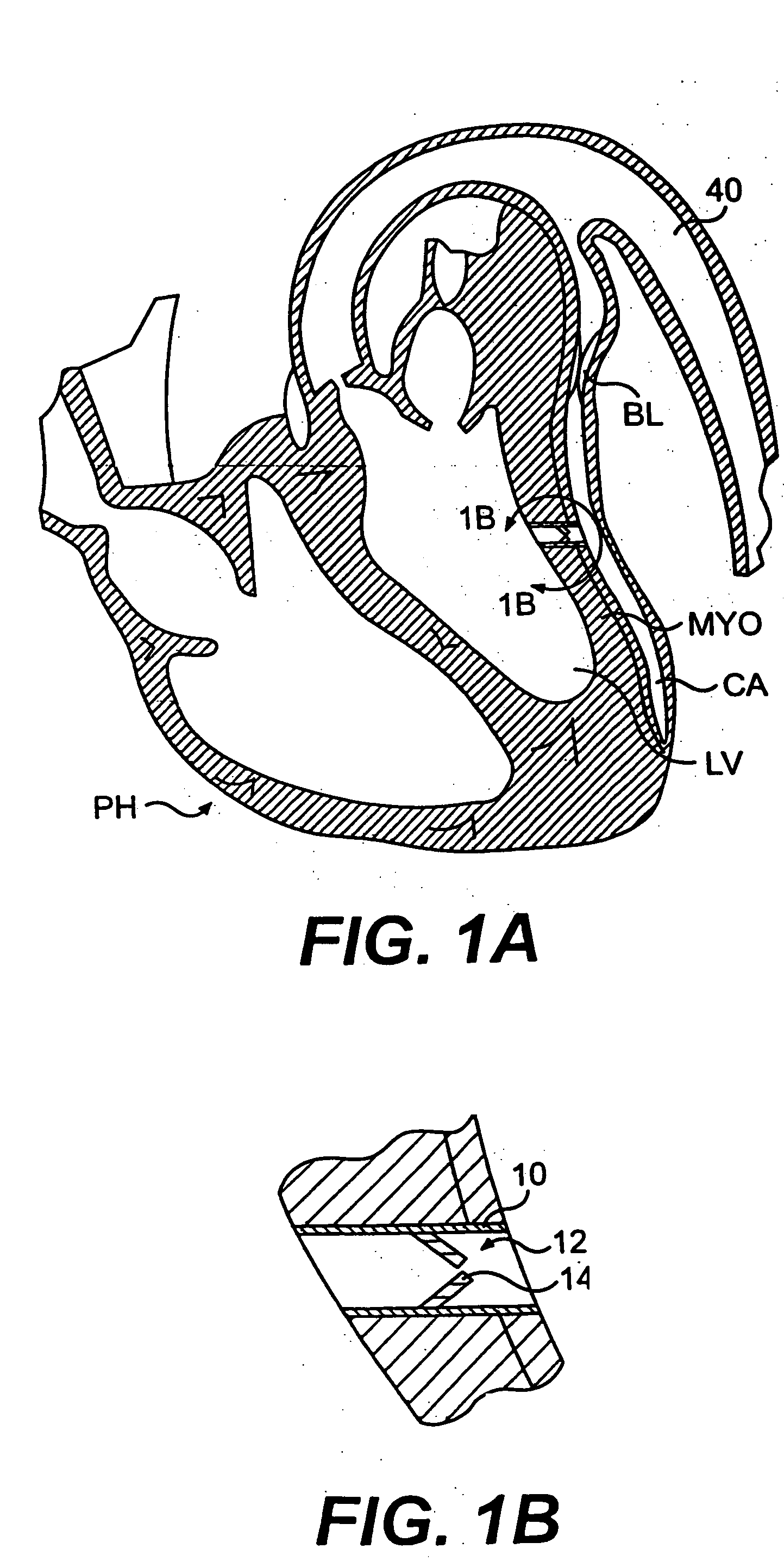
[0027] As is well known, the coronary artery branches off the aorta and is positioned along the external surface of the heart wall. Oxygenated blood that has returned from the lungs to the heart then flows from the heart to the aorta. Some blood in the aorta flows into the coronary arteries, and the remainder of blood in the aorta flows on to the remainder of the body. The coronary arteries are the primary blood supply to the heart muscle and are thus critical to life. In some individuals, atherosclerotic plaque, aggregated platelets, and / or thrombi build up within the coronary artery, blocking the free flow of blood and causing complications ranging from mild angina to heart attack and death. The presence of coronary vasospasm, also known as “variant angina” or “Prinzmetal's angina,” compounds this problem in many patients.

[0028] As used herein, the term “heart chamber” primarily refers to the interior, or lumenal, aspect of the left or right ventricle or the left or right atrium....


PUM


Abstract

Disclosed is a conduit that provides a bypass around a stenosis or occlusion in a coronary artery. The conduit is adapted to be positioned in the myocardium to provide a passage for blood to flow from a heart chamber to a coronary artery, at a site distal to the blockage or stenosis in the coronary artery. The conduit has a one-way valve positioned therein to prevent the backflow of blood from the coronary artery into the heart chamber.

Description

CROSS-REFERENCE TO RELATED APPLICATIONS [0001] This is a continuation of U.S. patent application Ser. No. 10 / 463,798, filed Jun. 18, 2003, now pending, which is a continuation application of U.S. patent application Ser. No. 09 / 368,393, filed on Aug. 4, 1999, now U.S. Pat. No. 6,641,610, and claims the benefit of U.S. Provisional Patent Application Ser. No. 60 / 099,777, filed Sep. 10, 1998, all of which are incorporated herein by reference.FIELD OF THE INVENTION [0002] This invention relates to apparatus and method for implanting a conduit to allow communication of fluids from one portion of a patient's body to another; and, more particularly, to a blood flow conduit to allow communication from a heart chamber to a vessel or vice versa, and / or vessel to vessel. Even more particularly, the invention relates to a left ventricular conduit and related conduit configurations for controlling the flow of blood through the conduit to achieve bypass of a stenosed or occluded coronary artery. B...

Claims


Application Information

Patent Timeline
Patent Type & Authority Applications(United States)
IPC IPC(8): A61M39/24A61F2/04A61B17/00A61F2/00A61F2/02A61F2/06A61F2/24A61F2/82A61F2/94
CPCA61F2/06A61F2/2493A61F2/848A61F2/94A61F2230/008A61F2002/821A61M39/24A61F2230/0067A61F2230/0078A61F2/958
Inventor WOLF, SCOTT J.FURNISH, GREG R.HALL, TODD A.PHELPS, DAVID Y.WILK, PETER J.BRIEFS, NANCY M.SANTAMORE, WILLIAMBURKHOFF, DANIEL
Owner WILK PATENT DEVMENT
Why Eureka
Try Eureka