Ventriculostomy reservoir

a technology of ventriculostomy and reservoir, which is applied in the field of surgical implantable valves, can solve the problems of brain tissue compression, impaired blood flow to the brain, and serious medical conditions, and achieve the effect of facilitating the detachable connection

Inactive Publication Date: 2006-05-25
CODMAN & SHURTLEFF INC
View PDF35 Cites 16 Cited by
  • Summary
  • Abstract
  • Description
  • Claims
  • Application Information

AI Technical Summary

Benefits of technology

[0009] The present invention generally provides a ventriculostomy reservoir device that is useful in treating hydrocephalus. The ventriculostomy reservoir device includes a base having an upper and lower opening, the upper opening defining an internal reservoir well, and a cap having an open bottom portion. The device further includes a flange element having a first portion disposed within a portion of the cap and a second portion extending distally beyond the open bottom portion of the cap and adapted for detachably mating with the internal reservoir well of the base. The detachable connection is facilitated by a snap fit element on the flange element that is adapted to cooperate with a complementary feature on the base to secure the flange element and the base together. The device also includes at least one sealing element disposed between the internal reservoir well and the flange element. The sealing element is adapted to provide a fluid tight seal between the base and the flange element when the base and the flange element are detachably mated.

Problems solved by technology

If left untreated, the increasing volume of fluid elevates the patient's intracranial pressure and can lead to serious medical conditions such as compression of the brain tissue and impaired blood flow to the brain.
One drawback of the conventional ventriculostomy reservoirs is the difficulty of manipulating the various components and assembling them into a fluid-tight and securely mated device within a patient.

Method used


Image

  • Ventriculostomy reservoir
  • Ventriculostomy reservoir
  • Ventriculostomy reservoir

Examples


Embodiment Construction

[0029] In general, the present invention provides a ventriculostomy reservoir device having a reservoir area and a cap positionable over the reservoir area. A snap connection and a sealing element connect the reservoir area to the cap and thereby provide a detachable, fluid-tight connection. In one aspect, the snap connection is formed between non-elastomeric, substantially rigid materials such that the reservoir area and the cap are securely mated, while the seal is formed of a more pliable material to facilitate a fluid tight seal.

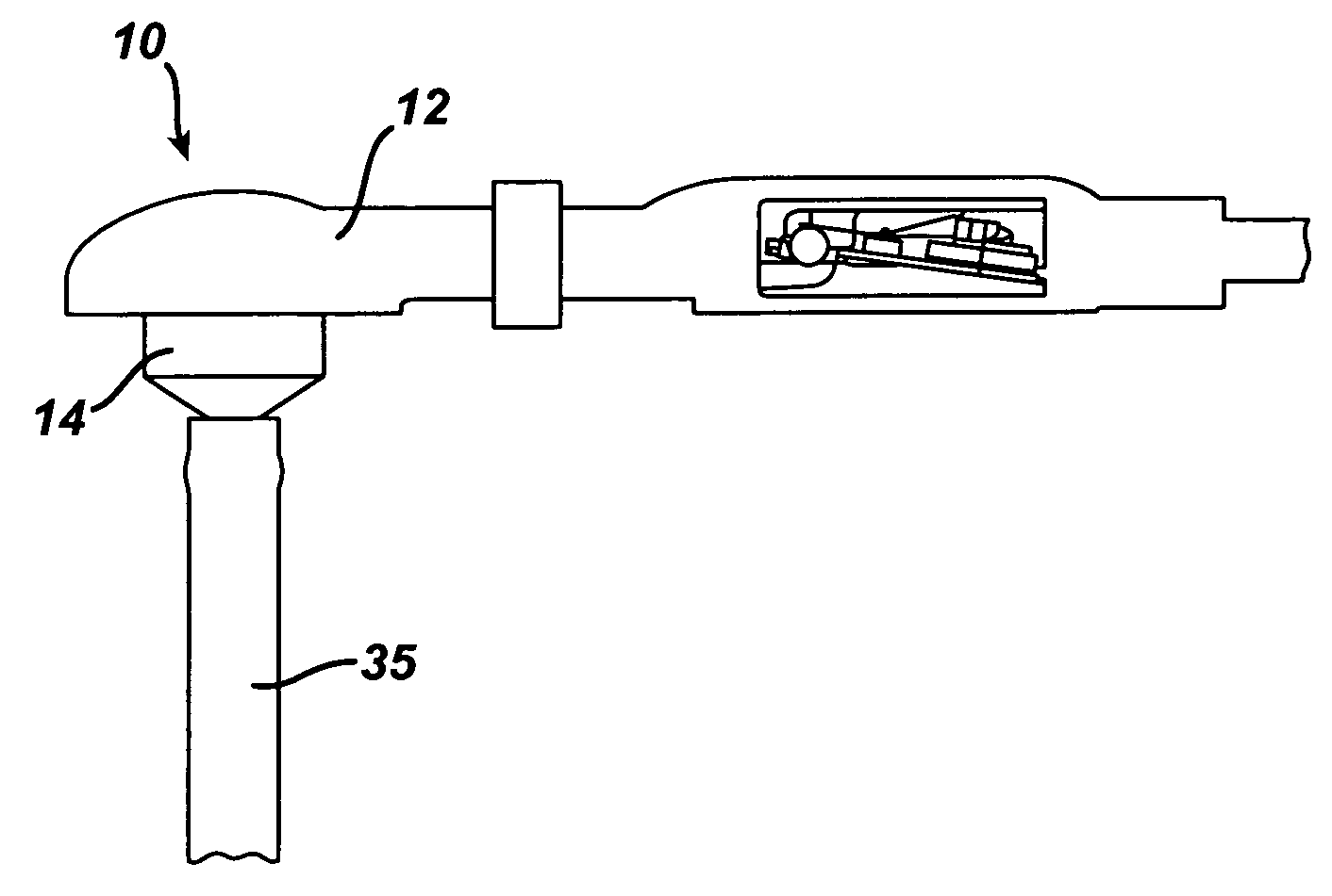
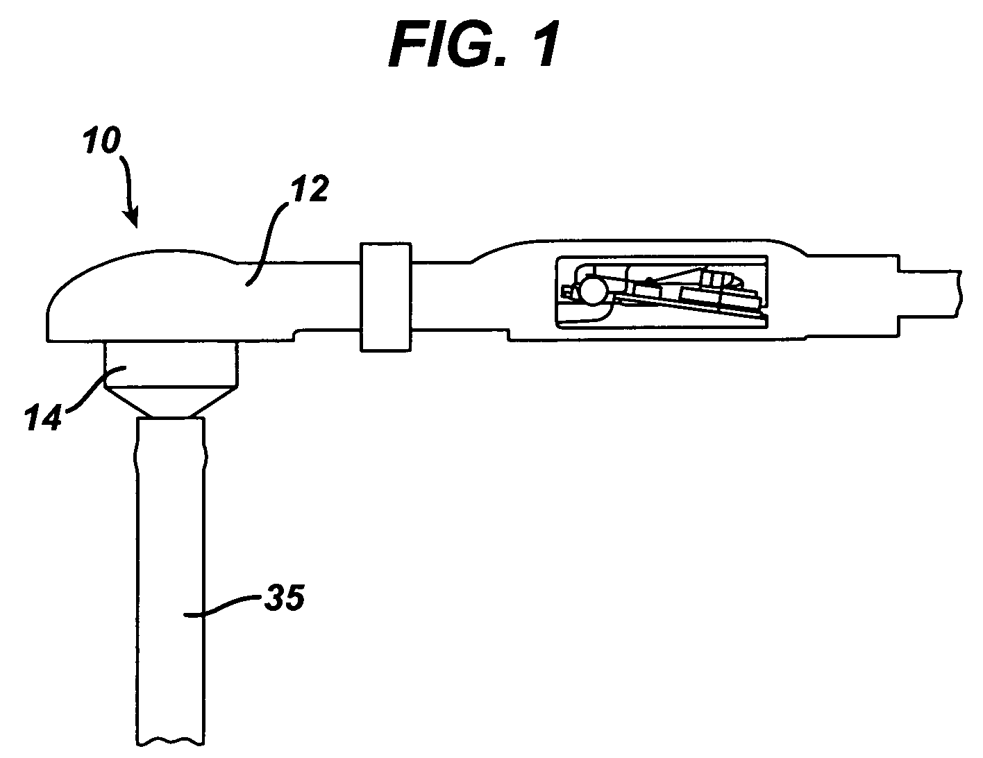
[0030]FIG. 1 illustrates an assembled ventriculostomy reservoir device 10, including a cap 12 and a base 14. The cap and the base are able to be mated to one another as described below and the assembled device encloses an internal reservoir well which can be sampled by inserting a sampling tool through cap 12.

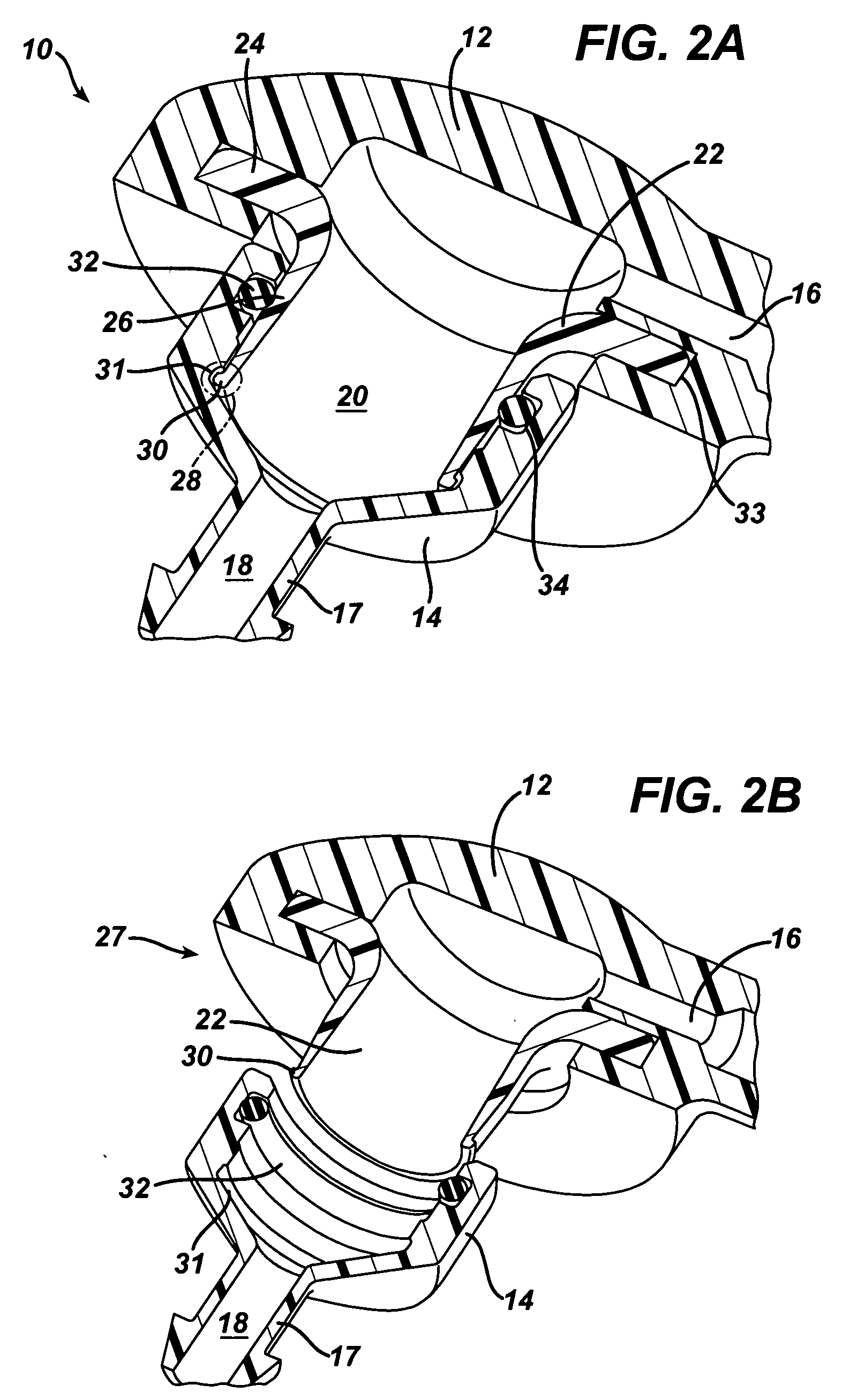
[0031]FIGS. 2A through 2C illustrate the construction of the device 10 pictured in FIG. 1. As shown, cap 12 includes a closed top and an open bot...


PUM


Abstract

A resealable ventriculostomy reservoir device is provided. The device includes a base having an upper and lower opening, the upper opening defining an internal reservoir well, and a cap having an open bottom portion. The device further includes a flange element having a first portion disposed within a portion of the cap and a second portion extending distally beyond the open bottom portion of the cap and adapted for detachably mating with the internal reservoir well of the base. The second portion of the flange element includes a snap fit element adapted to cooperate with a feature on the internal reservoir well to secure the flange element and the base together. A sealing element is disposed between the internal reservoir well and the flange element to provide a fluid tight seal between the base and the flange element when the base and the flange element are detachably mated.

Description

CROSS-REFERENCE TO RELATED APPLICATIONS [0001] Not applicable. STATEMENT REGARDING FEDERALLY SPONSORED RESEARCH [0002] Not Applicable. FIELD OF THE INVENTION [0003] The present invention relates to surgically implantable valves, and in particular to valves capable of resealable assembly and adapted for the drainage of cerebrospinal fluid from the ventricle of the brain. BACKGROUND OF THE INVENTION [0004] Hydrocephalus is a condition afflicting patients who are unable to regulate cerebrospinal fluid flow through their body's own natural pathways. Produced by the ventricular system, cerebrospinal fluid (CSF) is normally absorbed by the body's venous system. In a patient suffering from hydrocephalus, the cerebrospinal fluid is not absorbed in this manner, but instead accumulates in the ventricles of the patient's brain. If left untreated, the increasing volume of fluid elevates the patient's intracranial pressure and can lead to serious medical conditions such as compression of the bra...

Claims


Application Information

Patent Timeline
Patent Type & Authority Applications(United States)
IPC IPC(8): A61B19/00
CPCA61M27/006A61M2202/0464
Inventor KRAUS, ROBERT G.TAYLOR, ROBERTBUONANNO, JOHN
Owner CODMAN & SHURTLEFF INC
Why Eureka
Try Eureka