Glenoid prosthesis and method of implanting same

a technology of glenoid prosthesis and implanting method, which is applied in the field of glenoid prosthesis, can solve the problems of the risk of loosening of glenoid prosthesis, and achieve the effect of being easier to handl

Inactive Publication Date: 2006-05-25
SMITH & NEPHEW ORTHOPAEDICS
View PDF11 Cites 128 Cited by
  • Summary
  • Abstract
  • Description
  • Claims
  • Application Information

AI Technical Summary

Benefits of technology

[0010] It is thus one objective of the present invention to provide a glenoid prosthesis that is easier to handle than conventional prostheses, and with which a processing parallel to the normal line of the joint surface (i.e., perpendicular to the joint surface) is replaced by a processing and also implantation in the anterior / posterior (A-P) direction. These advantages are intended to apply to both a cement-free and a cemented version of the prosthesis.

Problems solved by technology

Furthermore, with conventional implants there is a risk of the loosening of the glenoid prosthesis.

Method used


Image

  • Glenoid prosthesis and method of implanting same
  • Glenoid prosthesis and method of implanting same
  • Glenoid prosthesis and method of implanting same

Examples


Embodiment Construction

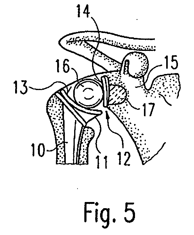
[0023] For better understanding of the context of the glenoid prosthesis in accordance with the invention, a shoulder-joint total prosthesis according to the state of the art will be described with reference to FIG. 5, which shows a humerus nail 10 with a bearing structure 11. The bearing structure 11 defines a concave bearing surface 13 for a joint or humerus ball 16. On the scapula side, the joint ball 16 is supported against a glenoid prosthesis 12, which has a bearing surface 14 that likewise has a concave curvature. The glenoid prosthesis 12 is anchored in the scapula, i.e. in the shoulder blade 15, where said anchoring is reinforced by an anchoring peg 17.

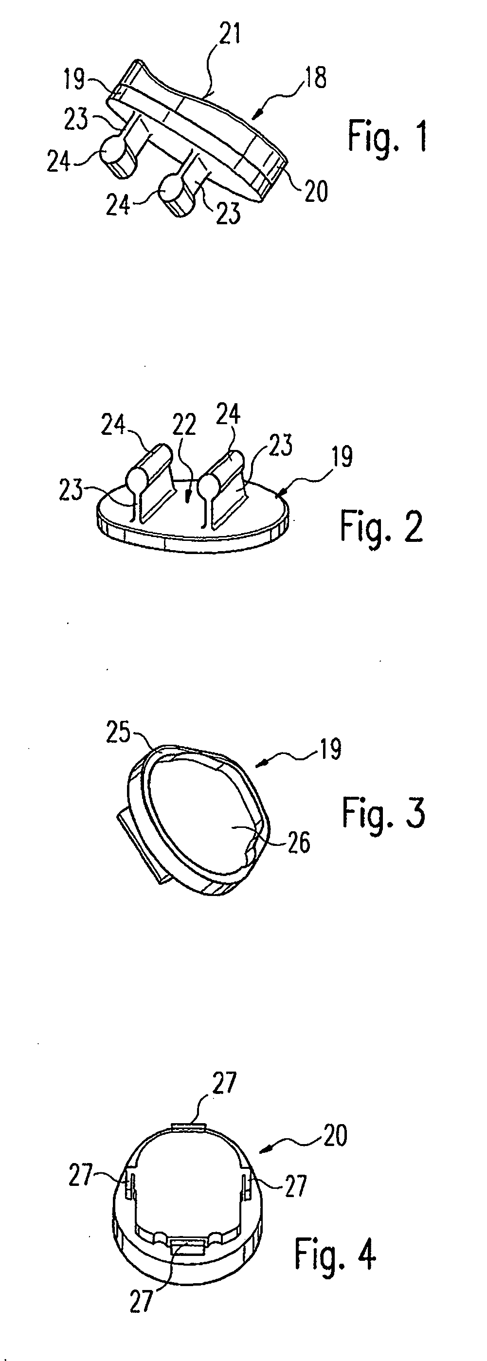
[0024] Embodiments of the present invention are concerned with further development of the glenoid prosthesis 12, as discussed with reference to FIGS. 1-4.

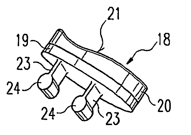
[0025]FIG. 1 shows a glenoid prosthesis 18 comprising a carrier shell 19 preferably made of a human-tissue-compatible metal, such as titanium or a titanium alloy, and a be...


PUM

PropertyMeasurementUnit
thicknessaaaaaaaaaa
thicknessaaaaaaaaaa
thicknessaaaaaaaaaa

Abstract

A glenoid prosthesis includes a bearing, the lateral side of which defines a concave bearing surface, and a carrier shell, the medial side of which comprises anchoring elements, wherein the medial side is generally flat. The prosthesis may be implanted in an anterior-posterior (A-P) by forming bores in the scapula in the A-P direction, wherein the anchoring elements extend into the bores. The scapula may be proceed to have a generally flat surface to correspond with the flat surface at the medial side of the prosthesis.

Description

CROSS-REFERENCE TO RELATED APPLICATIONS [0001] This application claims priority to German Application No. DE 10 2004 053 606.6, filed Nov. 5, 2004, the entire contents of which are incorporated herein by reference and should be considered a part of this specification. BACKGROUND OF THE INVENTION [0002] 1. Field of the Invention [0003] The invention relates to a glenoid prosthesis, and in particular relates to a prosthetic joint replacement for a shoulder joint, with a bearing shell the medial side of which, where appropriate, comprises anchoring elements and the lateral side of which defines a concave bearing surface. [0004] 2. Description of the Related Art [0005] Conventional shoulder joint replacement includes the replacement of either only the joint surface on the humerus side, i.e. the head of the humerus (hemi-arthroplasty), or the replacement of both joint surfaces, i.e. the head of the humerus and the glenoid fossa (total arthroplasty). Both monoblock and modular endoprosthe...

Claims


Application Information

Patent Timeline
Patent Type & Authority Applications(United States)
IPC IPC(8): A61F2/40
CPCA61F2/4081A61F2002/30112A61F2002/30125A61F2002/30158A61F2002/30387A61F2002/30433A61F2002/305A61F2002/30604A61F2002/30606A61F2002/30607A61F2002/30642A61F2002/30772A61F2002/30878A61F2002/30883A61F2002/30884A61F2002/30892A61F2002/30935A61F2002/4631A61F2220/0025A61F2220/0041A61F2230/0004A61F2230/0008A61F2230/0026A61F2250/0062A61F2310/00023A61F2310/00179A61F2310/00796
Inventor BAILIE, DAVID S.RINER, MARC A.
Owner SMITH & NEPHEW ORTHOPAEDICS
Why Eureka
Try Eureka