
Optical lens molding apparatus

a technology of optical lenses and molding apparatuses, which is applied in glass making apparatus, glass pressing apparatus, manufacturing tools, etc., can solve the problems of optical lenses produced using a conventional molding apparatus, prone to tilting or de-centering problems, and the expansion of mold cores, so as to minimize the tilting or de-centering of the optical axis and the effect of thermal expansion coefficien

Inactive Publication Date: 2006-06-01
ASIA OPTICAL CO INC
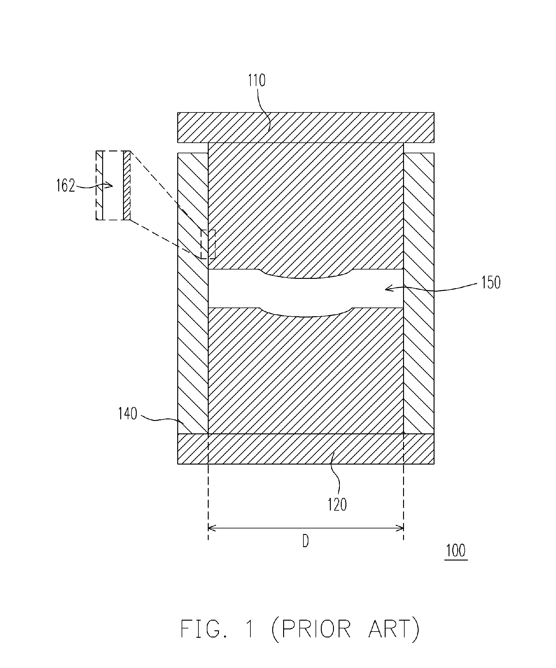
View PDF3 Cites 12 Cited by
  • Summary
  • Abstract
  • Description
  • Claims
  • Application Information

AI Technical Summary

Benefits of technology

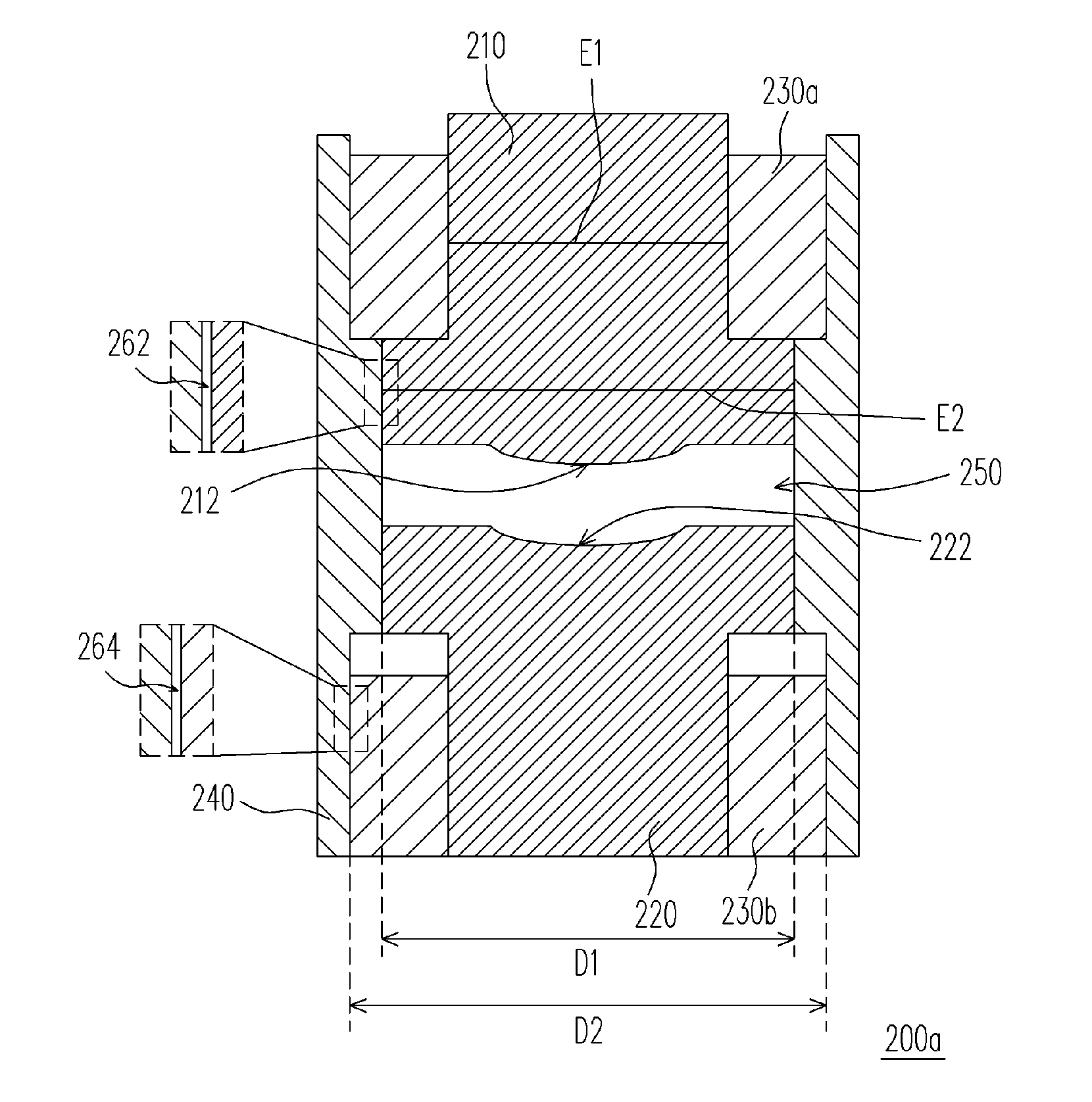
[0011] Accordingly, at least one object of the present invention is to provide an optical lens molding apparatus for minimizing the tilting or de-centering of the optical axis of molded lenses by adding a sleeve between an external sleeve and a mold core. The additional sleeve has a coefficient of thermal expansion greater than that of the external sleeve.
[0013] In the present invention, two internal sleeves are disposed inside the optical lens molding apparatus. Through a tight fitting of the two internal sleeves to the mold cores, tilting or de-centering of the first mold core at the high temperature environment of a molding process is reduced. Hence, the optical lens molding apparatus can provide a significant improvement to optical axis tilting and de-centering problem.

Problems solved by technology

However, at a high molding temperature, both the mold and the mold cores will expand leading to larger gaps.
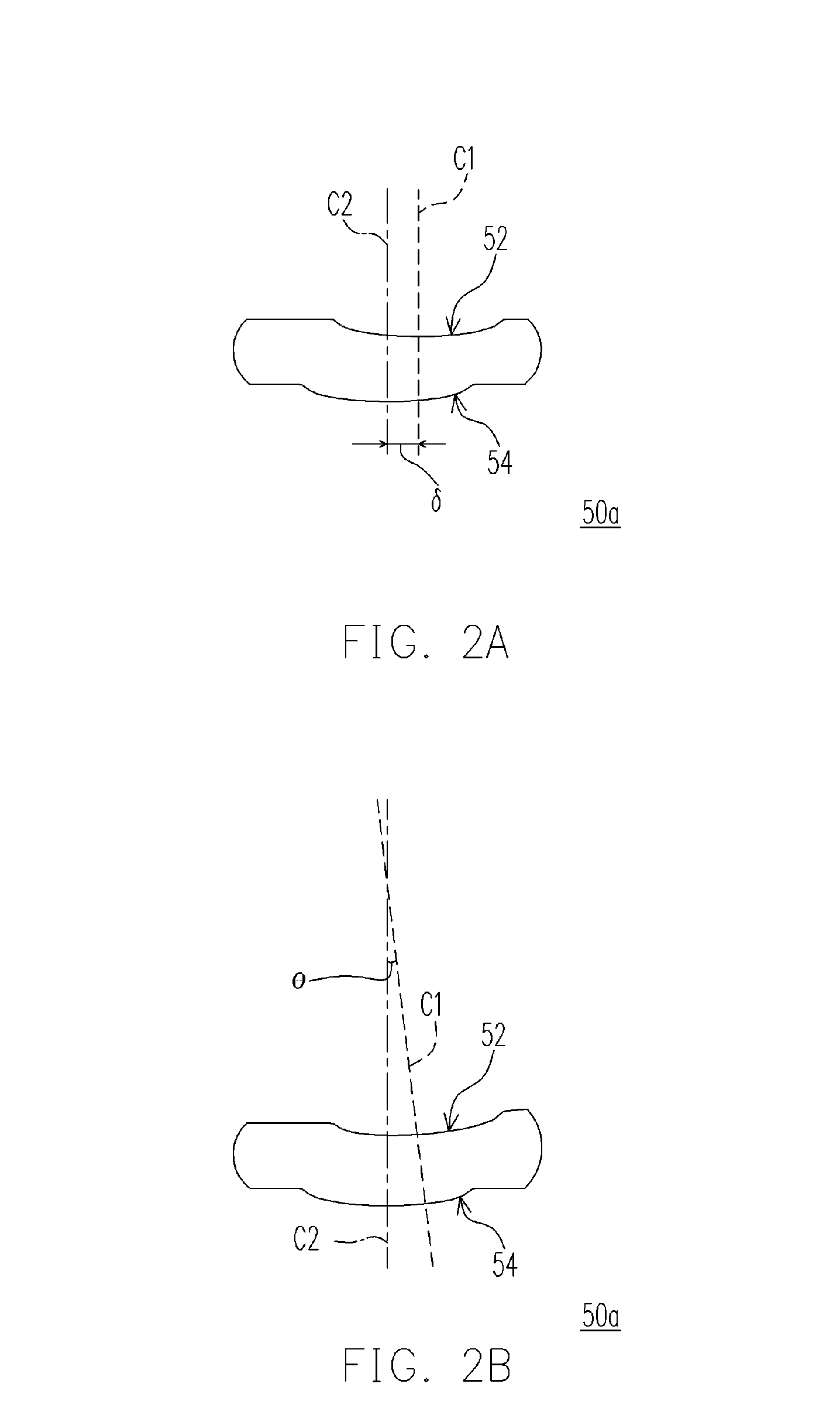
In other words, the optical lens produced using a conventional molding apparatus is liable to have tilting or de-centering problem.
This leads to some difficulties in finding the center in a centering process.
The inability to locate the correct position of the optical axis often leads to a significant drop in the yield of assembling products.

Method used


Image

  • Optical lens molding apparatus
  • Optical lens molding apparatus
  • Optical lens molding apparatus

Examples


Embodiment Construction

[0020] Reference will now be made in detail to the present preferred embodiments of the invention, examples of which are illustrated in the accompanying drawings. Wherever possible, the same reference numbers are used in the drawings and the description to refer to the same or like parts.

[0021]FIG. 3 is a schematic cross-sectional view showing the structure of an optical lens molding apparatus according to one embodiment of the present invention. The optical lens molding apparatus of the present invention mainly serves for molding a lump of material into an optical lens. The material to be molded into an optical lens is typically glass or optical polymer. In the present embodiment, the molding material is a gob of glass. However, the material that can be molded by the optical lens molding apparatus is not limited to glass. As shown in FIG. 3, the present embodiment provides an optical lens molding apparatus 200a essentially comprising an upper mold core 210, a lower mold core 220, ...


PUM

PropertyMeasurementUnit
Diameteraaaaaaaaaa
Coefficient of linear thermal expansionaaaaaaaaaa
Expansion enthalpyaaaaaaaaaa

Abstract

An optical lens molding apparatus comprising a first mold core, a second mold core, two internal sleeves and an external sleeve is provided. The first and the second mold core have a first coefficient of thermal expansion. The two internal sleeves are co-axially assembled with the first mold core and the second mold core respectively and have a second coefficient of thermal expansion. Furthermore, the external sleeve has a first inner diameter and a second inner diameter. The first mold core and the second mold core are co-axially assembled into the external sleeve having the first inner diameter such that a cavity is formed between the two mold cores. The two internal sleeves are co-axially assembled into the external sleeve having the second inner diameter. The external sleeve has a third coefficient of thermal expansion smaller than the first and the second coefficient of expansion.

Description

CROSS-REFERENCE TO RELATED APPLICATION [0001] This application claims the priority benefit of Taiwan application serial no. 93137014, filed on Dec. 1, 2004. BACKGROUND OF THE INVENTION [0002] 1. Field of the Invention [0003] The present invention relates to an optical lens molding apparatus. More particularly, the present invention relates to an optical lens molding apparatus that reduces optical axis from being tilted and de-centered. [0004] 2. Description of the Related Art [0005] Conventionally, the process of fabricating a non-spherical optical lens includes setting up a mold cavity with a mold and a pair of mold cores and then heating a gob of glass inside the mold cavity to soften the glass into whatever shape desired and obtain an optical lens after cooling. In general, small gaps between the mold cores and the mold are provided to ease assembling. However, at a high molding temperature, both the mold and the mold cores will expand leading to larger gaps. As a result, tilting...

Claims


Application Information

Patent Timeline
IPC IPC(8): C03B11/08
CPCC03B11/08C03B2215/03C03B2215/49C03B2215/60C03B2215/72Y02P40/57
Inventor WANG, MENGKUN
Owner ASIA OPTICAL CO INC
Learn More