Device for reduction of axial movement of the main shaft gears in a transmission with at least two countershafts

a technology of main shaft gears and countershafts, which is applied in the direction of gearing details, mechanical equipment, gearing, etc., can solve the problems that the gears cannot move axially any more, and achieve the effects of reducing the axial movement of the main shaft gear, increasing the force of the ring disc against the main shaft, and cost-effectively

Inactive Publication Date: 2006-06-01
ZF FRIEDRICHSHAFEN AG
View PDF8 Cites 9 Cited by
  • Summary
  • Abstract
  • Description
  • Claims
  • Application Information

AI Technical Summary

Benefits of technology

[0013] With reference to an especially advantageous extension of the invention it is suggested that the washer disc is arranged on the ring disc is dimensioned at least in the radial direction such that the leverage of the pressing of the ring disc against the main shaft is increased.
[0014] The innovative concept offers a cost effective and easily achievable solution through which the axial movement of the main shaft gear is reduced considerably.

Problems solved by technology

As a result, the gears cannot move axially any more.

Method used


Image

  • Device for reduction of axial movement of the main shaft gears in a transmission with at least two countershafts
  • Device for reduction of axial movement of the main shaft gears in a transmission with at least two countershafts

Examples


Embodiment Construction

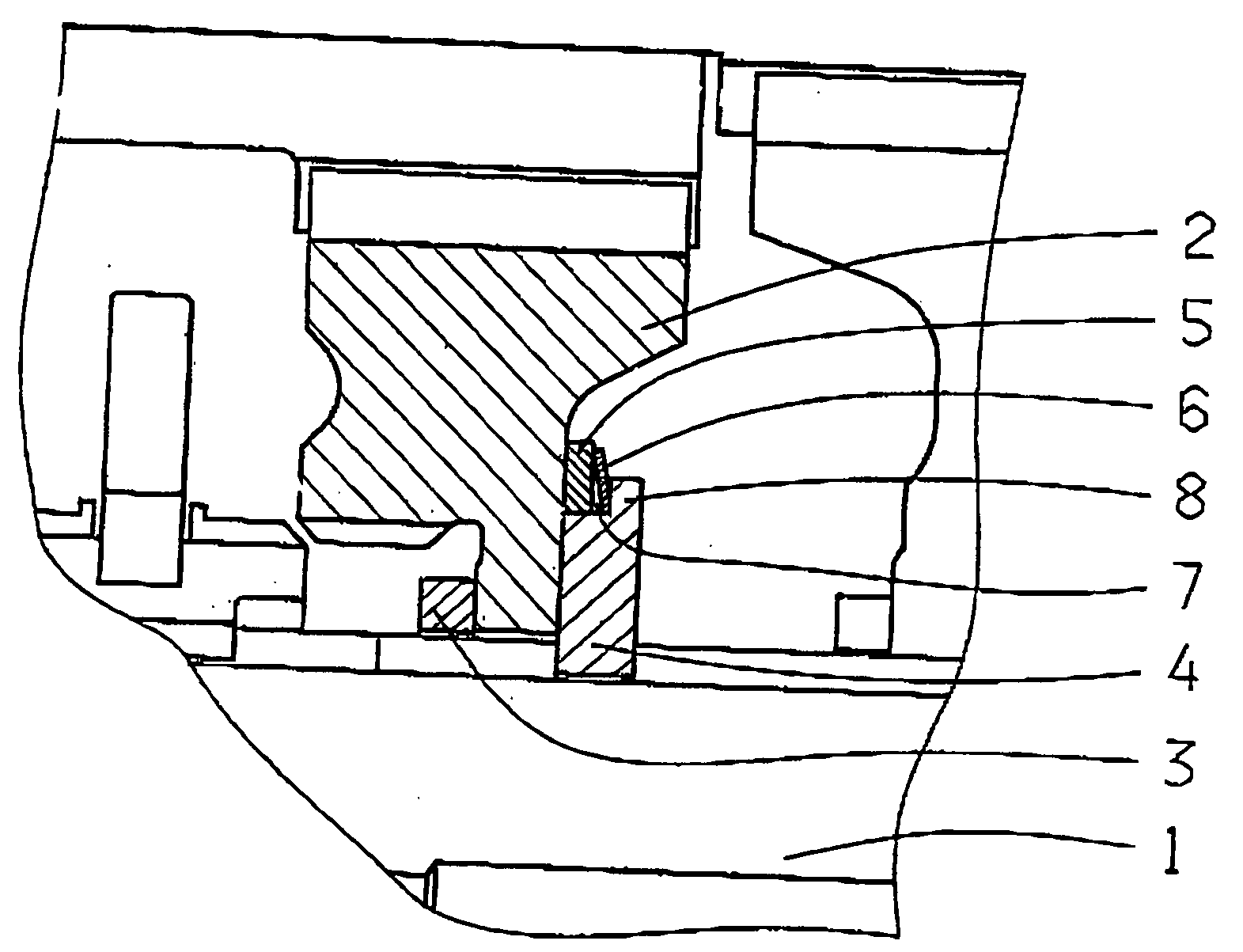
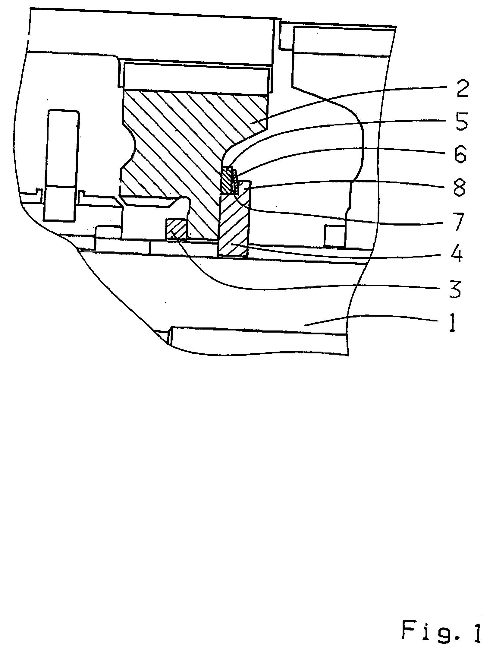
[0017] A main shaft 1 is shown in the FIGURE on which there is a main shaft gear 2 arranged between two washer discs 3 and 4 which hold the main shaft gear 2 axially. The washer discs 3 and 4 are fitted on to the main shaft 1 with respective slots so that they do not rotate.

[0018] To minimize the play of the main shaft gear 2 between the washer discs 3 and 4 is a device comprising of a ring disc 5 and a spring element constructed as a disc spring 6 which presses the main shaft gear 2 against the washer disc 3.

[0019] The ring disc 5 is arranged concentrically with the washer disc 4 which holds the main shaft gear 2 on to the main shaft 1 whereby washer disc 4 has a clearance 7 with the ring disc 5 and the spring element 6 when viewed radially on its side (towards the ring disc 5) and when viewed axially in the direction of the main shaft 2. In this way the spring element 6 when viewed axially is arranged between an upper part 8 of the washer disc 4 and the ring disc 5 and presses t...


PUM


Abstract

A device for the reduction of axial movement of the main shaft gears (2) in a transmission containing at least two countershafts. The main shaft gears (2) are held axially by two washer discs (3, 4) which is designed to be a pressing device (5, 6) on the main shaft (1) for at least one of the main shaft gears (2) against the washer disc (3) holding the main shaft gear (2) axially.

Description

[0001] This application claims priority from German Application Serial No. 10 2004 057 126.0 filed Nov. 26, 2004. FIELD OF THE INVENTION [0002] The following invention relates to a device for reduction of the axial movement of the main shaft gears in a transmission with at least two countershafts. BACKGROUND OF THE INVENTION [0003] In the state of the art for transmissions with at least two countershafts, the free gears which serve as main shaft gears are placed radially in both the gears of the countershafts. The main shaft gears are placed on the main shaft in the axial direction with the help of washer discs whereby a washer disc of the free gear is arranged between the washer discs arranged on the main shaft. There is a disadvantage here whereby due to production tolerances and due to the gaps required for oiling, a large play arises so that when the mass of the free gears vibrate as a result of the wobbling of the main shaft or as a result of rotational movements and thus cause...

Claims


Application Information

Patent Timeline
Patent Type & Authority Applications(United States)
IPC IPC(8): F16H3/38
CPCF16H3/093F16H57/0006F16H57/12Y10T74/19233Y10T74/19228Y10T74/19223Y10T74/19284Y10T74/19219
Inventor RENNER, STEFAN
Owner ZF FRIEDRICHSHAFEN AG
Why Eureka
Try Eureka