

Variable valve operating apparatus for internal combustion engine
- Summary
- Abstract
- Description
- Claims
- Application Information
AI Technical Summary
Benefits of technology
Problems solved by technology
Method used
Image

Examples
first embodiment
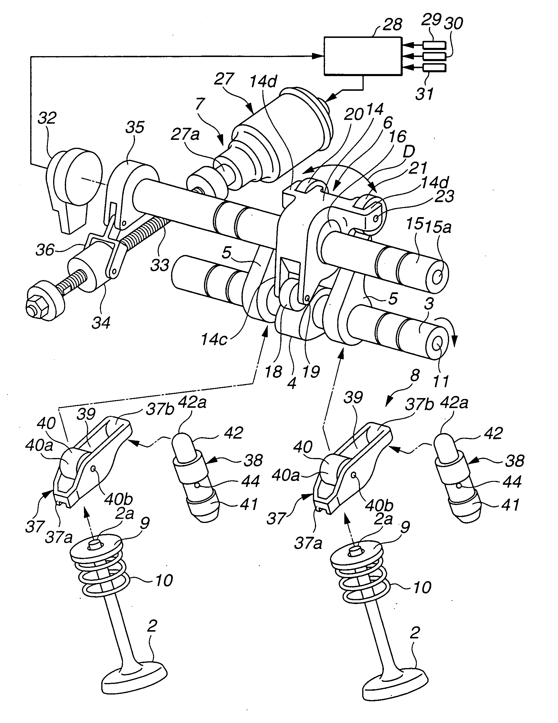
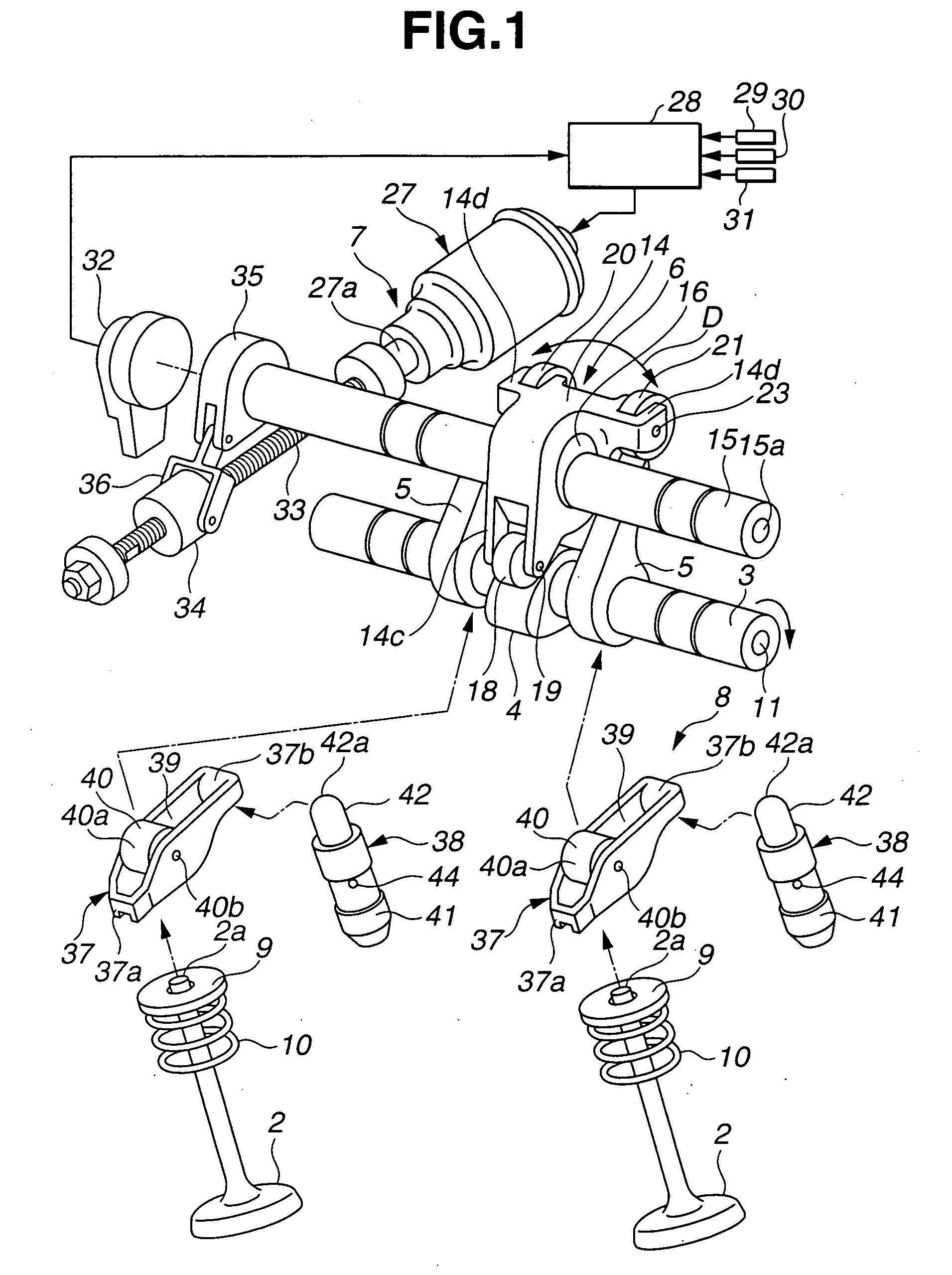
[0048] Referring now to FIGS. 1-8, a variable valve operating apparatus for an internal combustion engine according to the present invention, is explained. In this embodiment, the variable valve operating apparatus is used on an intake side of the engine with two intake valves per cylinder. As illustrated in FIGS. 1, 2 and 4, the variable valve operating apparatus includes two intake valves 2, 2 slidably mounted on cylinder head 1 through valve guides, not shown, drive shaft 3 disposed above cylinder head 1 and rotatively driven by a crankshaft of the engine, drive cam 4 disposed on an outer circumferential surface of drive shaft 3, a pair of rocker cams 5, 5 operative to open and close intake valves 2, 2, lift varying mechanism 6 that mechanically links drive cam 4 to rocker cams 5, 5 to vary the lift of intake valves 2, 2, actuation mechanism 7 for actuating a control section of lift varying mechanism 6 which controls an operating position of lift varying mechanism 6, and swing me...
second embodiment
[0105] An operation of the variable valve operating apparatus of the second embodiment will be explained hereinafter. When the engine is operated in a low speed range, controller 28 outputs control current to rotate electric actuator 27 in a predetermined direction. Ball screw shaft 33 is rotated by the output torque from electric actuator 27, causing ball nut 34 to linearly move to a predetermined linear position on ball screw shaft 33. In this state, control shaft 15 is held in rotational positions as shown in FIGS. 11 and 12 by link bracket 36 and link arm 35. In the rotational positions, central axis P1 of eccentric control cam 16 is located on the right-upper side with respect to central axis P of control shaft 15. Thus, rocker arm 114 is placed in an upward pivotal position with respect to control shaft 15. On the other hand, rocker cams 105, 105 are biased by the spring forces of torsion springs 123, 123 such that cam noses 113c, 113c are urged onto pivotal portions 120a, 121...
third embodiment
[0137] Further, each of rocker cams 205, 205 includes base portion 12 divided into two parts as explained in the As shown in FIG. 22, one of the two parts of base portion 12 has a rectangular shape, and the other thereof with cam lobe 113 has a generally trapezoidal shape. Single generally L-shaped bracket 59 is provided in common to rocker cams 205, 205. Bracket 59 is mounted to the rectangular parts of base portions 12, 12 of respective rocker cams 205, 205. Specifically, bracket 59 includes vertically extending base 59a fixed to outer surfaces of the rectangular parts of base portions 12, 12 by means of bolts 50, 50, and free end portion 59b connected with base 59a and extending substantially perpendicular thereto. Coil spring 60 is installed between free end portion 59b of bracket 59 and retainer 24e that laterally projects from an upper end portion of bearing bracket 24c. Rocker cams 205, 205 are biased by the spring force of coil spring 60 to rotate in the counterclockwise di...
PUM
 Abstract
Description
Claims
Application Information