Ignition timing control system for internal combustion engine

Inactive Publication Date: 2006-06-01
HONDA MOTOR CO LTD
View PDF2 Cites 13 Cited by
  • Summary
  • Abstract
  • Description
  • Claims
  • Application Information

AI Technical Summary

Benefits of technology

[0007] The present invention has been made to provide a solution to the above-described problems, and an object thereof is to provide an ignition timing control system for internal combustion engines

Problems solved by technology

In general, the internal combustion engine sometimes experiences variation in combustion state between the cylinders thereof (i.e. variation in heat energy generated by combustion), and in such a case, generated torque varies between the cylinders, which causes variation in the engine speed and vibrations, resulting in degraded drivability.
Further, when the engine is used as a power source of a vehicle, there is a fear of occurrence of surging.
In contrast, the ignit

Method used


Image

  • Ignition timing control system for internal combustion engine
  • Ignition timing control system for internal combustion engine
  • Ignition timing control system for internal combustion engine

Examples


Example

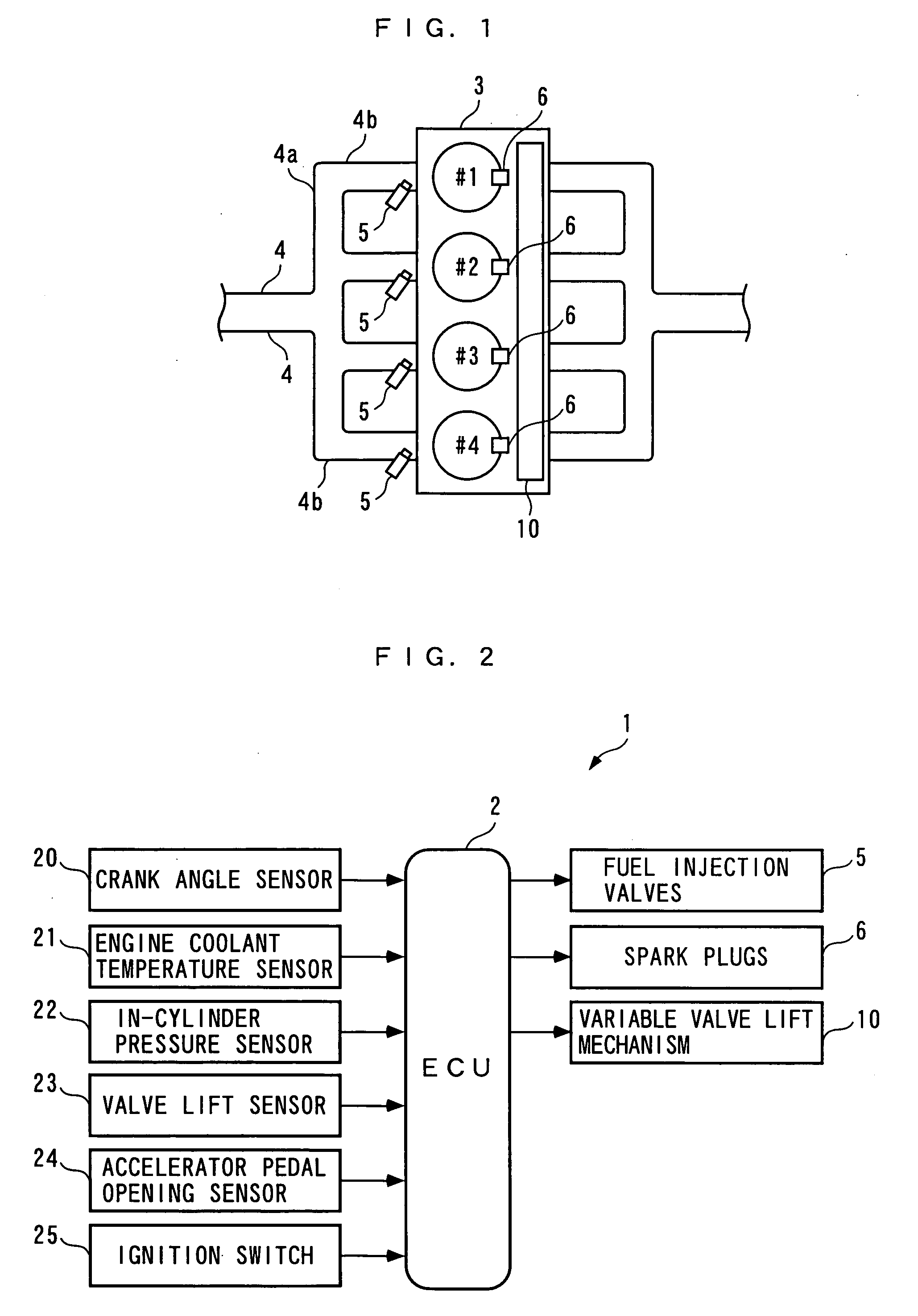
[0042] Hereafter, an ignition timing control system according an embodiment of the present invention will be described with reference to the drawings. The ignition timing control system 1 includes an ECU 2, as shown in FIG. 2. As described hereinafter, the ECU 2 carries out control processes, including an ignition timing control process, depending on operating conditions of an internal combustion engine (hereinafter simply referred to as “the engine”) 3.

[0043] Referring to FIG. 1, the engine 3 is an in-line four-cylinder gasoline engine installed on a vehicle, not shown, and includes first to fourth cylinders #1 to #4 (a plurality of cylinders). The engine 3 has an intake pipe 4 connected to the four cylinders #1 to #4 via four branch portions 4b of an intake manifold 4a.

[0044] In the branch portions 4b, fuel injection valves 5 are inserted at respective locations upstream of intake ports, not shown, for the cylinders. During operation of the engine 3, each fuel injection valve 5 ...


PUM


Abstract

An ignition timing control system for internal combustion engines, which is capable of preventing occurrence of variation in engine speed and vibrations which can be caused due to variation in combustion state between the cylinders, to thereby improve drivability. The ECU 2 of the ignition timing control system 1 calculates a statistically processed value Pmi_ls#i according to the in-cylinder pressure Pcyl#i, and calculates an averaging target value Piav_cmd by weighted averaging of a minimum value Pmi_ls_min1 and a second minimum value Pmi_ls_min2 within a predetermined range of the statistically processed value. The ECU 2 calculates a correction value DIGCMP#i by performing a limiting process for setting the optimization correction value DIGOP#i for control of the ignition timing to a limit value on the advanced side, on the averaging correction value DIGPIAV#i for causing the statistically processed values Pmi_ls#i to follow the averaging target value Piav_cmd, such that the statistically processed values Pmi_ls#i becomes maximum. The ignition timing IGLOG#i is calculated for each cylinder based on the correction value DIGCMP#i.

Description

BACKGROUND OF THE INVENTION [0001] 1. Field of the Invention [0002] The present invention relates to an ignition timing control system for an internal combustion engine, which controls ignition timing of the engine according to the in-cylinder pressure. [0003] 2. Description of the Related Art [0004] Conventionally, an ignition timing control system for an internal combustion engine, which controls the ignition timing of the engine using the in-cylinder pressure thereof has been proposed e.g. in Japanese Laid-Open Patent Publication (Kokai) No. 2003-262177. This ignition timing control system calculates the difference between the maximum value of the in-cylinder pressure detected by the in-cylinder pressure sensor and the value of the same at the top dead center position of the compression stroke, and when the difference is smaller than a predetermined threshold value, the ignition timing is determined to be too retarded, so that the ignition timing is controlled to be advanced by a...

Claims


Application Information

Patent Timeline
IPC IPC(8): F02P5/153
CPCF02D41/1408F02P5/153Y02T10/46Y02T10/40
Inventor YASUI, YUJISHINOZAKI, KOICHIROSATO, MASAHIRO
Owner HONDA MOTOR CO LTD
Why Eureka
Try Eureka