Radiating fin assembly

a technology of radiating fins and assembly parts, which is applied in the direction of electrical apparatus construction details, light and heating apparatuses, laminated elements, etc., can solve the problems of deformation of the fastening lug, inconvenient assembly and disassembly, and still the conventional radiating fins, so as to achieve easy assembly/disassembly and the effect of easy assembly

Inactive Publication Date: 2006-06-01
YANG JOHNSON
View PDF7 Cites 7 Cited by
  • Summary
  • Abstract
  • Description
  • Claims
  • Application Information

AI Technical Summary

Benefits of technology

[0009] The primary objective of the present invention is to provide a radiating fin assembly that can be assembled/disassembled easily and can be used repeatedly, wherein a folding edge is formed at opposite sides of the radiating fin, respectively, and a flexible slot is defined in the folding edge and located at both sides of the locki...

Problems solved by technology

However, such conventional radiating fin still has some disadvantages as follows:
First, it may have its own advantage if the fastening lug 13 is engaged with the other surface of the notch 14, however, such arrangement doesn't facilitate assembly and disassembly.
Second, the user has to bend the fastening lug 13, and this will cause permanent deformation to the fastening lug 13.
When the user disassembles the radiating fin 10, although the already distorted fastening lug 13 can be bent a...

Method used


Image

  • Radiating fin assembly
  • Radiating fin assembly
  • Radiating fin assembly

Examples


Embodiment Construction

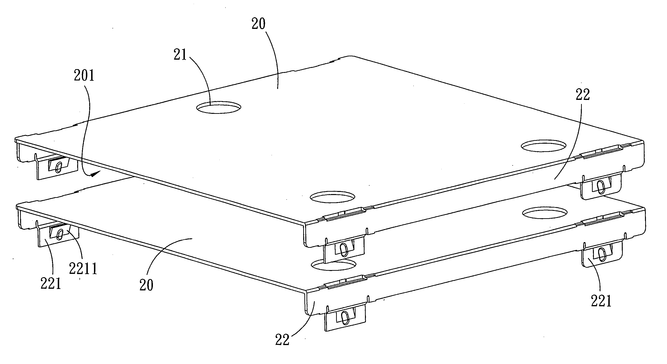
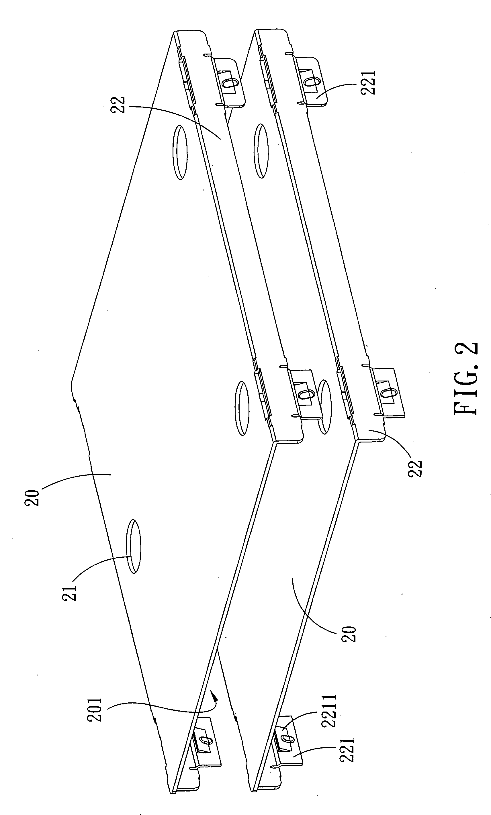
[0017] Referring to FIGS. 2-5, a radiating fin assembly in accordance with the present invention comprises a plurality of radiating fins 20 stacked together.

[0018] The radiating fin 20 is a plate formed with a plurality of guiding holes 21 at the upper surface thereof. At two opposite sides of the radiating fin 20 is formed a folding edges 22, and at both ends of the folding edge 22 is formed a locking protrusion 221 connected to the folding edge 22 by an inward inclined neck portion 222. A flexible slot 223 is defined in the folding edge 22 and located at both sides of the locking protrusion 221, and a plurality of notches 23 are defined in the radiating fin 20 and located correspondingly to the locking protrusions 221, so that the locking protrusions 221 of one radiating fin 20 can be engaged in the notches 23 of another radiating fin 20.

[0019] A flexible hook 2211 is formed on each of the locking protrusions 221 and located correspondingly to the undersurface 201 of the radiati...


PUM


Abstract

A radiating fin assembly comprises a plurality of radiating fins stacked together, wherein a folding edge is formed on opposite sides of the radiating fins, at both ends of the folding edge is formed a locking protrusion and a neck portion, a flexible slot is defined in the folding edge and located at both sides of the locking protrusion, and a plurality of notches are defined in the respective radiating fins, so that locking protrusions of one radiating fin are allowed to be engaged in the notches of another radiating fin. A flexible hook is formed on each of the locking protrusions and located correspondingly to a undersurface of the radiating fin, a rib is disposed on the flexible hook and connected to the locking protrusion, and at both sides of the respective locking protrusions and the notches are correspondingly arranged a plurality of positioning members.

Description

BACKGROUND OF THE INVENTION [0001] 1. Field of the Invention [0002] The present invention relates to a radiating fin, and more particularly to a radiating fin assembly that can be assembled and disassembled easily without distortion. [0003] 2. Description of the Prior Art [0004] A conventional radiating fin 10 as shown in FIG. 1 comprises a plurality of locking protrusions 12 formed on the folding edges 11 thereof, a notch 14 is defined in the edge of the locking protrusions 12 so that two radiating fins 10 can be assembled together through the engagement of the locking protrusions 12 and the notch 14. However, at the front end of the conventional locking protrusions 12 usually are formed differently shaped fastening lugs 13. After two radiating fins 10 are stacked together, the user has to bend the fastening lug 13 and make it abut against another surface of the notch 14, so that the radiating fins 10 can be assembled each firmly. However, such conventional radiating fin still has ...

Claims


Application Information

Patent Timeline
IPC IPC(8): H05K7/20F28F3/02H01L21/48H01L23/367
CPCF28F3/02H01L21/4882H01L23/3672H01L2924/0002H01L2924/00
Inventor YANG, JOHNSON
Owner YANG JOHNSON
Why Eureka
Try Eureka