Self-locating feature for a pi-joint assembly

a self-locating and assembly technology, applied in the field of pi-joint assembly and method, can solve the problems of non-value-added work, complicated assembly procedures, etc., and achieve the effect of reducing was

Active Publication Date: 2006-06-01
THE BOEING CO
View PDF43 Cites 17 Cited by
  • Summary
  • Abstract
  • Description
  • Claims
  • Application Information

AI Technical Summary

Benefits of technology

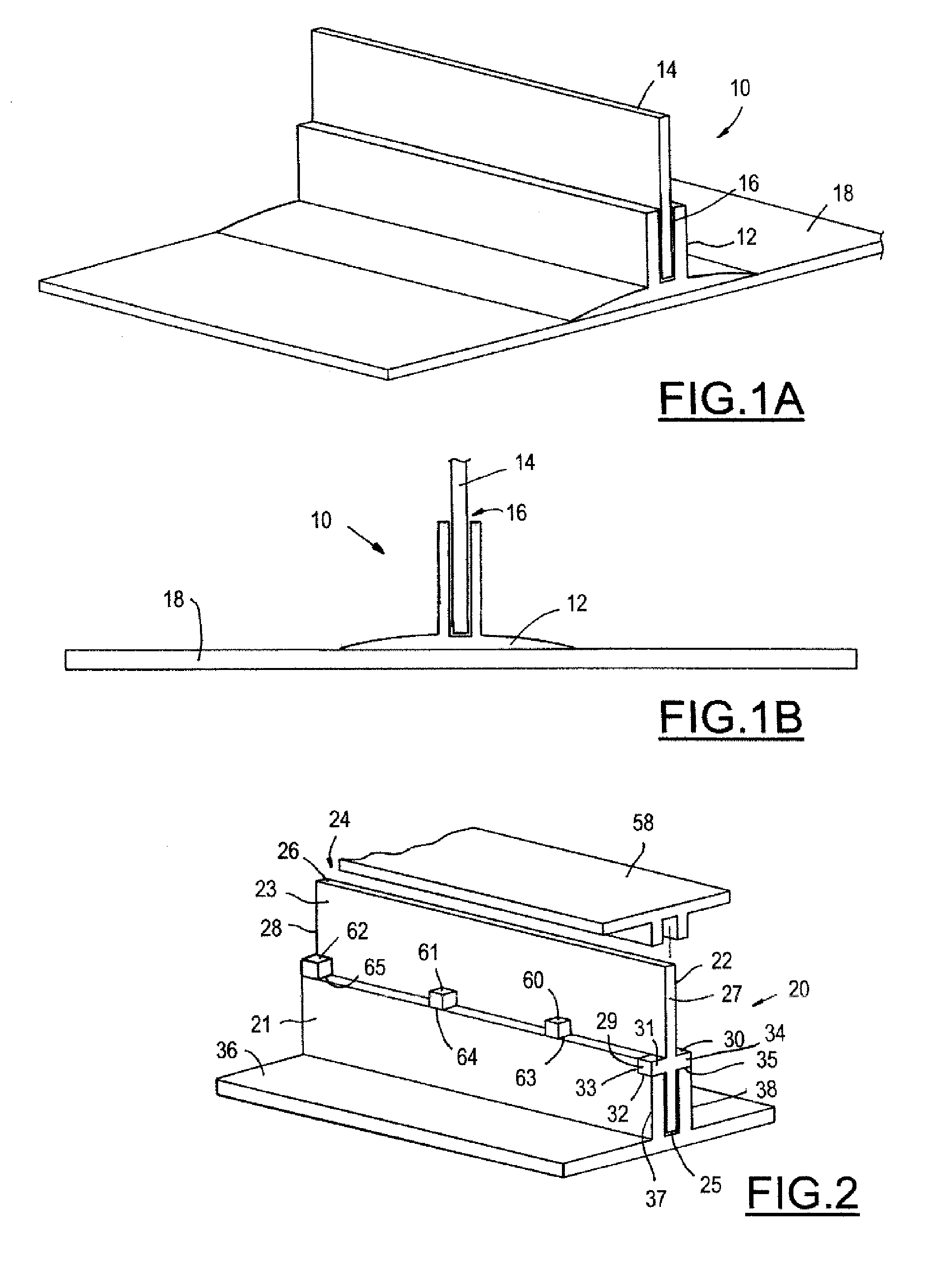
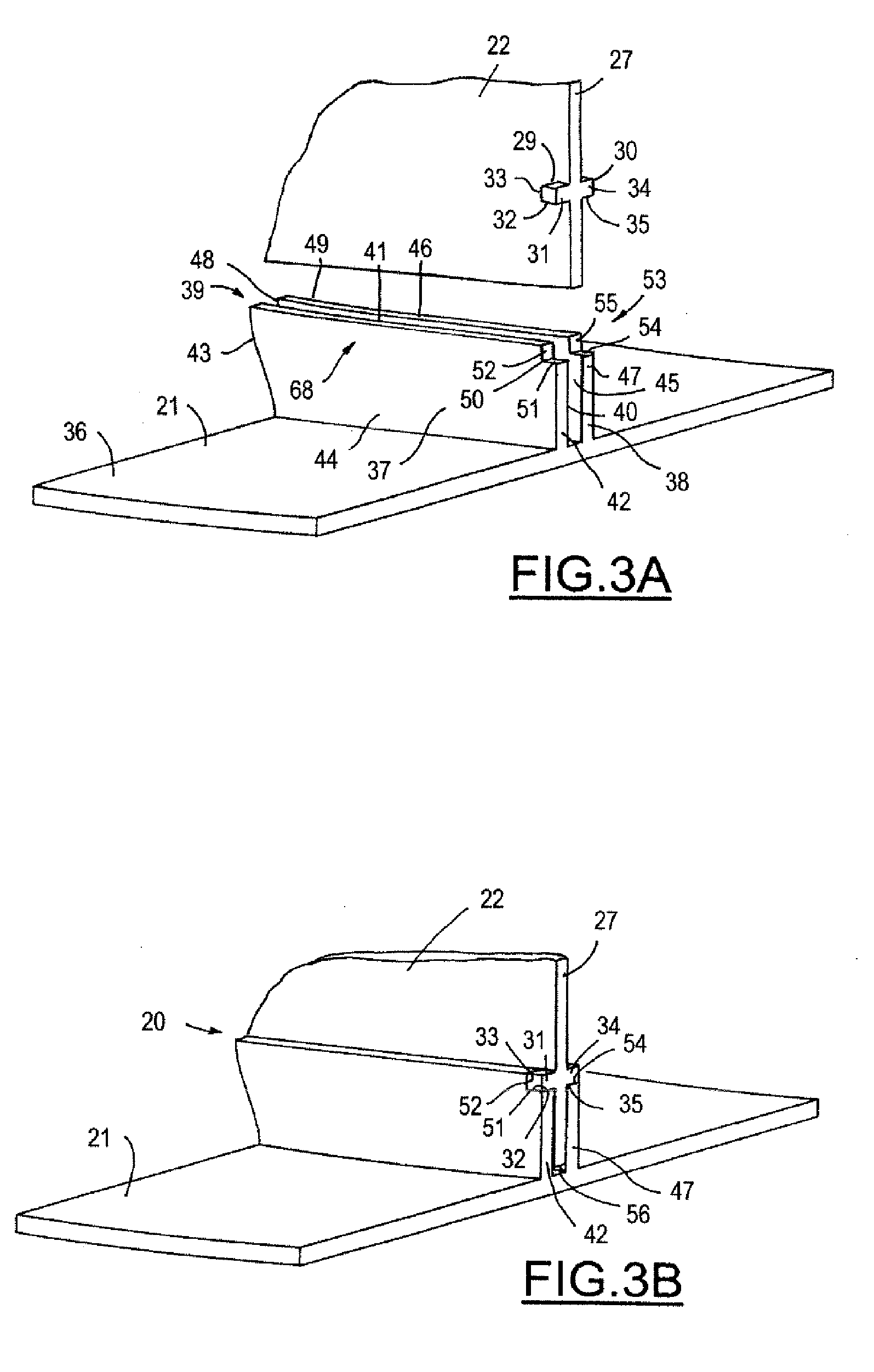
[0009] A self-locating feature for a pi-joint assembly is provided. The self-locating feature for a pi-joint assembly of the present invention utilizes some of the general concepts mentioned above in creating a novel and inventive pi-joint assembly. It eliminates waste by allowing the substructure and the member to be self-locating in a more efficient manner. The self-locating features provide horizontal control, vertical co

Problems solved by technology

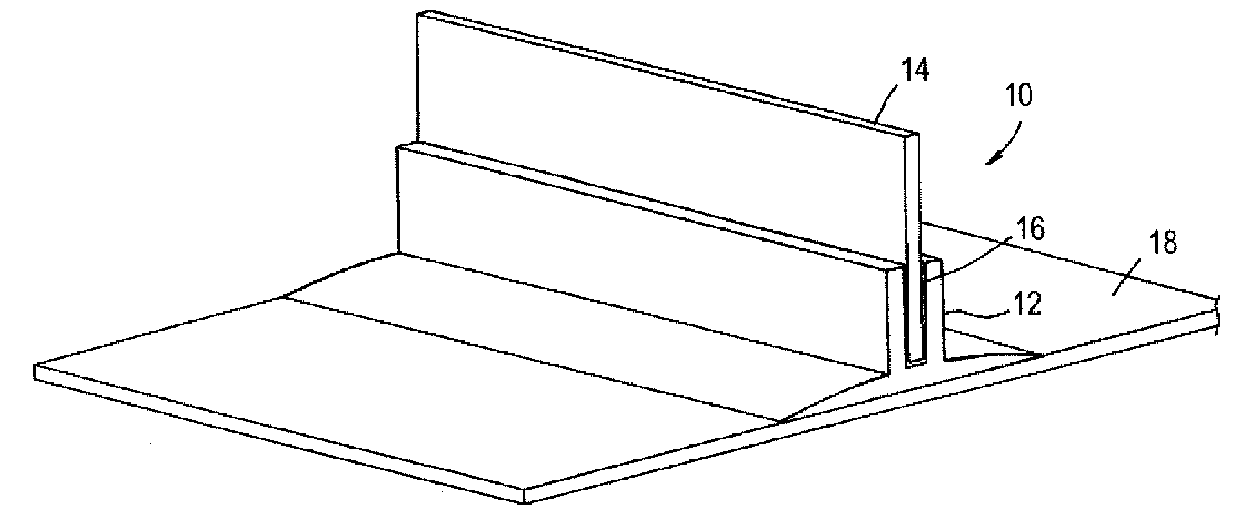
However, a disadvantage of such joints is the complicated assembly procedures required in order to properly align the parts prior to applying the adhesive 16 to secure the web 14 to the pi-member 12.
The additional steps of locating, drilling, cleaning, reassembly, fastening and unfastening as mentioned

Method used


Image

  • Self-locating feature for a pi-joint assembly
  • Self-locating feature for a pi-joint assembly
  • Self-locating feature for a pi-joint assembly

Examples


second embodiment

[0043]FIG. 4 is an isomeric view of a self-locating feature for a pi-joint assembly 70 in accordance with a second embodiment the present invention being used to advantage. The assembly 70 includes a member 71, a substructure 72 connected to the member 71, and a filler 77. The substructure 72 has two lands 73, 74, a boss 75 located on the front side of the substructure and a boss 76 located on the back side of the substructure. The two lands 73, 74 are positionally oriented into the two notches of the member 71, thereby locating the horizontal and vertical direction of the leading side of the substructure 72 with respect to the member 71. The two bosses 75, 76 are positionally oriented at the trailing side upon of the pair of axially elongated legs, thereby locating the vertical direction of the trailing side of the substructure 72. The two lands 73, 74 and the two bosses 75, 76 together provide a single orientation by which the substructure 72 may be positioned into the member 71. ...

third embodiment

[0045]FIG. 5 is an isomeric view of a self-locating feature for a pi-joint assembly 78 in accordance with a third embodiment the present invention being used to advantage. The assembly 78 includes a member 79, a substructure 80 connected to the member 79, and a filler 85. The substructure 80 has four lands 81, 82, 83, 84. Two lands 81, 82 are located on the leading side of the substructure and two lands 83, 84 are located on the trailing side of the substructure. Of which, two lands 81, 83 are located on the front side of the substructure and two lands 82, 84 are located on the back side of the substructure. The lands 81, 82, 83, 84 are positionally oriented in opposite direction into the four notches of the member 79, thereby locating the horizontal and vertical direction of the leading side and the trailing side of the substructure 80 with respect to the member 79. Moreover, the inventive self-locating features of the lands as described herein enable the precise depth control and ...


PUM

PropertyMeasurementUnit
Angleaaaaaaaaaa
Areaaaaaaaaaaa
Depthaaaaaaaaaa

Abstract

A self-locating feature for a pi-joint assembly is provided. The pi-joint assembly includes a substructure, a member coupled to the substructure. The substructure includes one or more land extending above one of a front side and a back side of the substructure. The land includes an outer surface, a depth location control surface and an edge location control surface. The member includes a base, a pair of axially elongated leg extending from the base to define a channel therebetween, and one or more notch located in one of the pair of axially elongated leg. The notch includes a depth contact location control surface and an edge contact location control surface, wherein the depth location control surface of the land of the substructure is correspondingly coupled to the depth contact location control surface of the notch located in one of the axially elongated leg, and the edge location control surface of the land of the substructure is correspondingly coupled to the edge contact location control surface of the notch located in one of the axially elongated leg. A method of assembling a pi-joint assembly of the present invention is also provided.

Description

[0001] This invention was made with Government support under SCRA Subrecipient Agreement No. 2001-508, awarded by the Department of the Navy. The Government has certain rights in this invention.RELATED APPLICATIONS [0002] The present invention is related to application (Attorney Docket 04-0385 (BOE 0527 PA)) entitled “Minimum Bond Thickness Assembly Feature Assurance” filed simultaneously herewith and incorporated by reference herein. TECHNICAL FIELD [0003] The present invention relates generally to a pi-joint assembly and method thereof, and more particularly, to a self-locating feature for a pi-joint assembly. BACKGROUND DESCRIPTION [0004] Pi-joint assemblies are beginning to be more prevalent as the choice for assembling two structural elements together, whether or not the structure is a static or dynamic structure, such as is a structure used on an airplane. More importantly, the pi-joint assembly affords a way in which to connect structural components together, especially when ...

Claims


Application Information

Patent Timeline
IPC IPC(8): B23K9/12
CPCF16B5/08F16B11/006F16B17/008F16B5/0012
Inventor KILWIN, JEFFREY J.NEWCOMER, RONALD J.FREEMAN, PHILIP L.
Owner THE BOEING CO
Why Eureka
Try Eureka