Wafer transfer mechanism

a transfer mechanism and wafer technology, applied in the direction of charge manipulation, hoisting equipment, furnaces, etc., can solve the problems of transfer error, inability to position the wafer w,

Inactive Publication Date: 2006-06-01
ASM JAPAN
View PDF9 Cites 384 Cited by
  • Summary
  • Abstract
  • Description
  • Claims
  • Application Information

AI Technical Summary

Benefits of technology

[0021] In yet another aspect, the present invention which can accomplish one or more of the above objects provides (A) a plasma processing chamber, (B) a thermal CVD chamber, and (C) a thermal processing chamber, each of which is provided with the transfer mechanism of any of th

Problems solved by technology

However, in a processing chamber in which a plasma, for example, is used for a given process of a wafer (e.g. plasma CVD), because a temperature of a workpiece to be transferred from the processing chamber is relatively hi

Method used


Image

  • Wafer transfer mechanism
  • Wafer transfer mechanism
  • Wafer transfer mechanism

Examples


Embodiment Construction

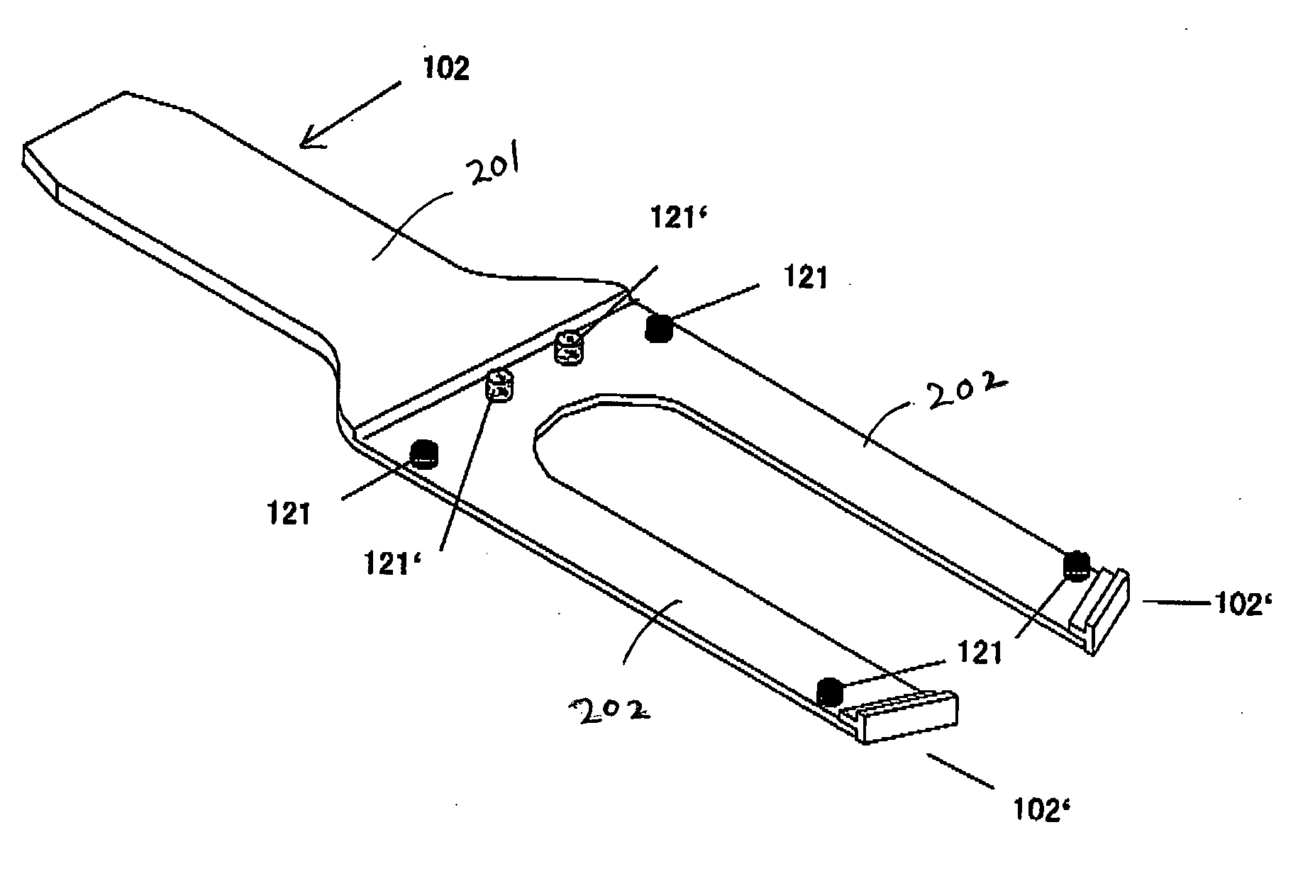
[0037] As described above, in an aspect, the present invention provides a transfer mechanism for transferring a workpiece, which comprises: (i) an arm member, (ii) a movement mechanism, and (iii) a positioning member.

[0038] The arm member comprises multiple supporting projections protruding from a top surface thereof for contacting and supporting a back side of the workpiece. The supporting projections have an area contacting the back side of the workpiece, which is less than an area of the top surface of the arm member which would have been in contact with the back side of the workpiece had the supporting projections not been provided. By reducing the area contacting the back surface of the workpiece, it becomes easier to slide the workpiece on the arm member even at high temperatures. In an embodiment, the contacting area of the supporting projections may be less than 50% (including 40%, 30%, 20%, 10%, 5%, 1%, and ranges between any two numbers of the foregoing), preferably 10% o...


PUM


Abstract

A transfer mechanism for transferring a workpiece includes an arm member including a tip projection provided at a tip end thereof for contacting a periphery of the workpiece and restricting movement of the workpiece. The arm member further includes multiple supporting projections protruding from a top surface thereof for contacting and supporting a back side of the workpiece.

Description

BACKGROUND OF THE INVENTION [0001] 1. Field of the Invention [0002] The present invention generally relates to an apparatus and a method for transferring a workpiece such as a semiconductor wafer to and from a storage section, and more particularly, relates to an apparatus and a method which can transfer a workpiece to a prescribed position in a storage section. [0003] 2. Description of the Related Art [0004] A process of semiconductor manufacturing includes a step of transferring a sheet of semiconductor wafer from a wafer-storing cassette to a processing chamber or a step of transferring a sheet of semiconductor wafer from a processing chamber to another processing chamber. FIG. 1 is a perspective view of a conventional transfer mechanism typically used for such transferring steps. (See U.S. Pat. No. 6,305,898, the disclosure of which is incorporated herein by reference in its entirety.) The transfer mechanism 1 has an arm 2 which can hold a semiconductor wafer W at the front ther...

Claims


Application Information

Patent Timeline
IPC IPC(8): B65G49/07
CPCH01L21/68707
Inventor TSUJI, NAOTAMORI, YUKIHIROHAGINO, TAKASHI
Owner ASM JAPAN
Why Eureka
Try Eureka