Precision timing light for internal combustion engine and method of use

a timing light and internal combustion engine technology, applied in the direction of engine ignition, machine/engine, mechanical equipment, etc., can solve the problems of large error in measuring ignition timing, affecting the proper function and performance of modern engines, and affecting the perception of ignition timing by observers, so as to improve the ignition timing measurement

Inactive Publication Date: 2006-06-01
COMPETITION CAMS
View PDF8 Cites 9 Cited by
  • Summary
  • Abstract
  • Description
  • Claims
  • Application Information

AI Technical Summary

Benefits of technology

[0013] According to a first aspect of the invention, the ignition timing light includes a focused light source, a securing member to permanently or removably fix the light source to the engine or engine compartment, an ignition indication sensor, a varying indication locator, such as a mark on a rotating engine member, and a control box having a readout and a retard/advance functionality to manipulate when the focused light source flashes. A narrow, focused light beam emitted from the focused light source provides for precise alignment of the reflected beam with the locator provided on the rotating engine member. Also, because the securing member fixes the focused light source at a single location, measurement error caused, for example, by lighting effects associated with tr

Problems solved by technology

One problem associated with hand-held devices such as Michalski and Becker is that the ignition timing perceived by an observer will vary from the true ignition timing, because, for example, the user observes the shadows cast by the timing and scale marks due to lighting effects associated with the handheld device, rather than the marks themselves, when determining timing.
Therefore, because both the handheld device and the observer can be positioned at any location, the handheld devices impart a large amount of error in measuring ignition timing.
This error can be de

Method used


Image

  • Precision timing light for internal combustion engine and method of use
  • Precision timing light for internal combustion engine and method of use
  • Precision timing light for internal combustion engine and method of use

Examples


Embodiment Construction

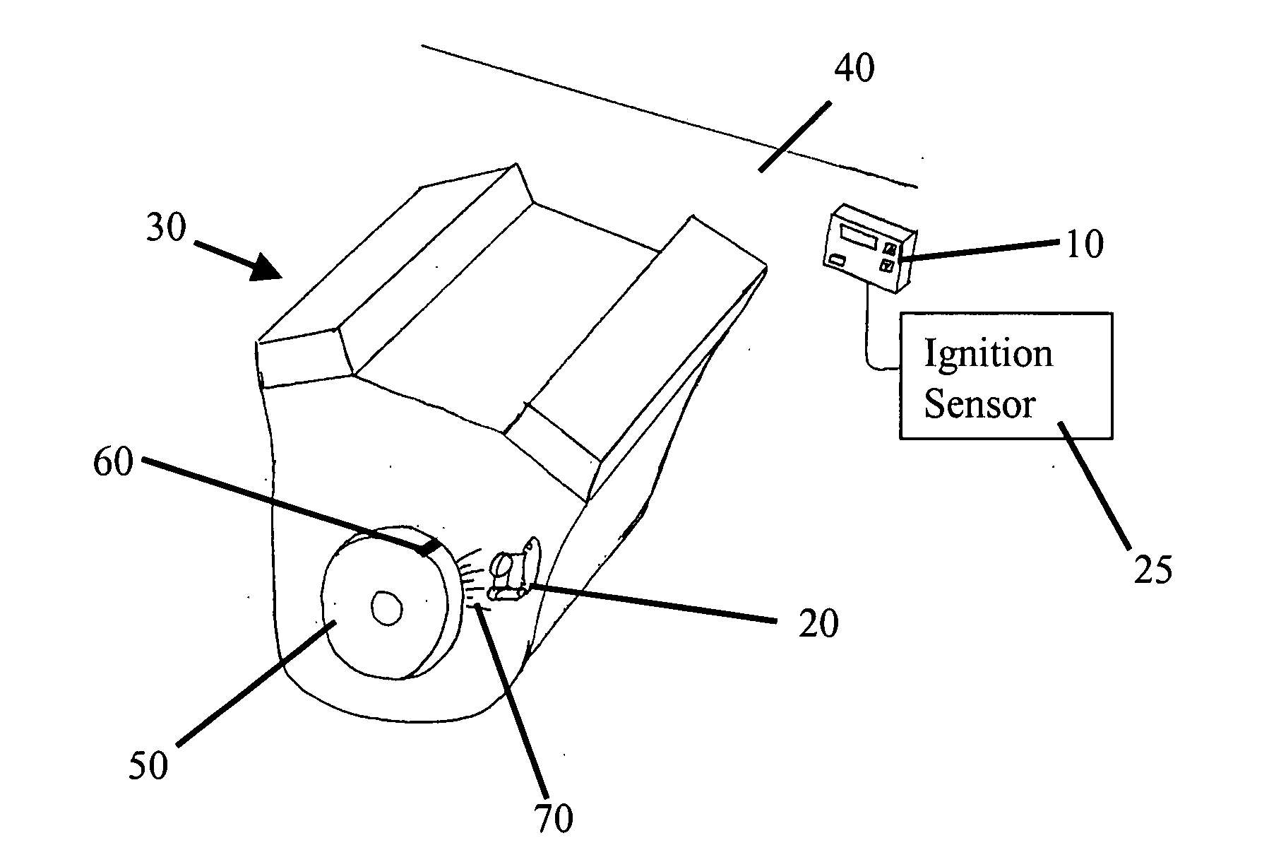
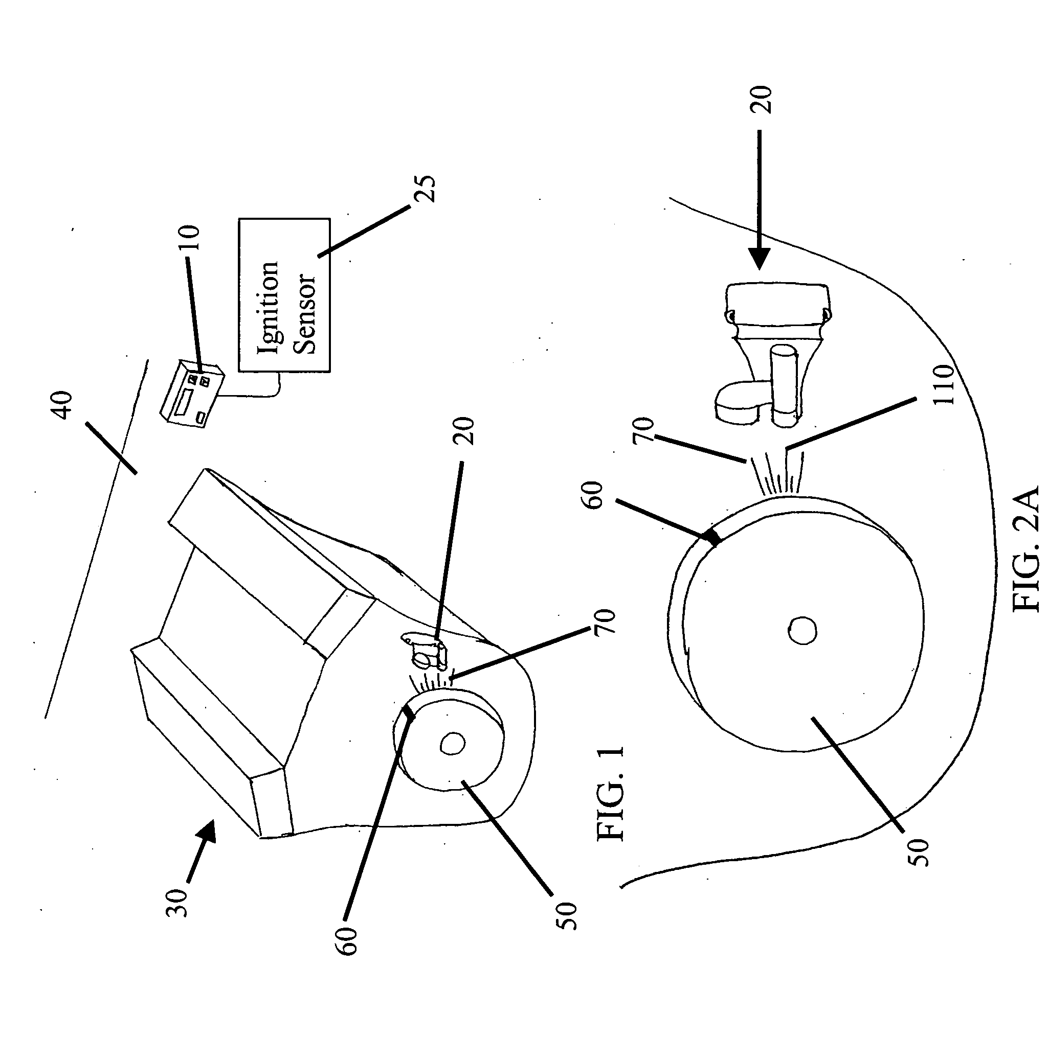
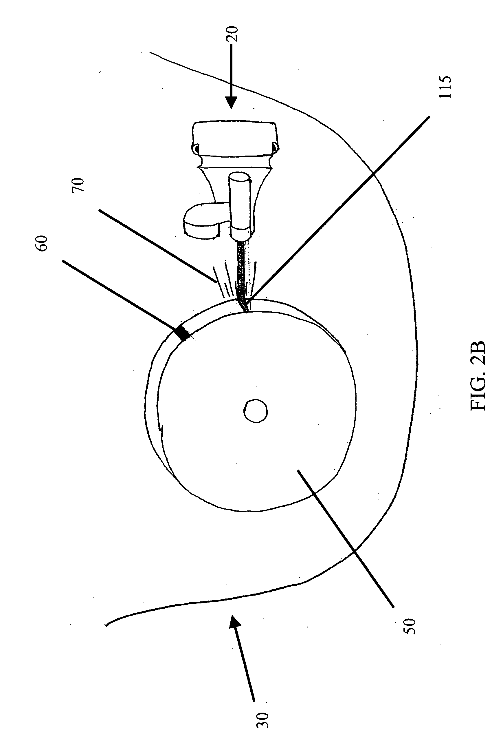
[0022] The present invention relates to an ignition timing device for measuring the ignition timing of an internal combustion engine, an embodiment of the present invention comprising a control box 10, a light assembly 20, and an ignition indication sensor 25. The control box 10, light assembly 20, and the ignition indication 25 sensor communicate, for example, via a wired, wireless, or fiber optic link, and are powered, for example, via an internal power source, such as an internal battery, or via connection to a vehicle battery. FIG. 1 illustrates an engine compartment having an engine 30 and a firewall 40. In this embodiment, the control box 10 is fixably located within the engine compartment. It is within the scope of the present invention, though, that the control box 10 could be located at any location or be usable remotely, such as in a hand-held device. A rotating engine member or other component 50, such as a standard pulley, is attached to an end of or otherwise rotates vi...


PUM


Abstract

An ignition timing device for measuring ignition timing that includes a focused light source, a securing member, an ignition indication sensor, and a control box. The focused light source permanently or removably attaches to an engine or engine compartment in close proximity to a rotating portion of the engine having marks that, when aligned with fixed timing marks or a reflection point, indicate ignition timing. The ignition timing device flashes the focused light source in response to receiving ignition detection signals from the ignition indication sensor. The control box has a capability to advance or retard the flashing of the focused light source in response to the ignition signal to allow advance or retard of engine ignition timing through, for example, adjustment to the distributor of the engine.

Description

BACKGROUND OF THE INVENTION [0001] 1. Field of the Invention [0002] This invention relates to a timing light for use with an internal combustion engine to accurately measure ignition timing, particularly a timing light having a focused light source permanently or removably attached onto or near an engine for which timing information is desired. [0003] 2. Discussion of Related Art [0004] As an internal combustion engine operates, pistons slidable within one or more cylinders cause a crankshaft within the engine to rotate by means of connecting rods attached both to the pistons and the crankshaft. In internal combustion engines of the gasoline type, the pistons compress an air / fuel mixture while moving toward an end of the cylinders. A spark plug then ignites the air / fuel mixture, causing the piston to slide down the cylinder, thereby rotating the crankshaft. Ignition timing refers to the location of a piston within a cylinder relative to the instant the spark plug fires. Ignition ret...

Claims


Application Information

Patent Timeline
IPC IPC(8): F02P17/00
CPCF02P17/06
Inventor BROTHERS, PAULTURNPAUGH, RON
Owner COMPETITION CAMS
Why Eureka
Try Eureka