Lens actuating device, camera module and portable electronic equipment

a technology of actuating device and lens, which is applied in the direction of mounting, optics, instruments, etc., can solve the problems of resin motor mounts having a decreased strength, deteriorating workability in assembling, and poor utilization of mounting space by second motor mounts in different directions, so as to reduce the sense of incongruity in shooting

Inactive Publication Date: 2006-06-01
SHARP KK
View PDF12 Cites 7 Cited by
  • Summary
  • Abstract
  • Description
  • Claims
  • Application Information

AI Technical Summary

Benefits of technology

[0033] In this embodiment, the direction to the subject in shooting can be made orthogonal to a surface o

Problems solved by technology

In the lens actuating device for the zoom lens and the focusing lens, a zooming motor and a focusing motor are fixed to first and second different motor mounts, respectively, so that an increased number of components including resin bearings are required, which deteriorates workability in assembling.
Besides, the

Method used


Image

  • Lens actuating device, camera module and portable electronic equipment
  • Lens actuating device, camera module and portable electronic equipment
  • Lens actuating device, camera module and portable electronic equipment

Examples


first embodiment

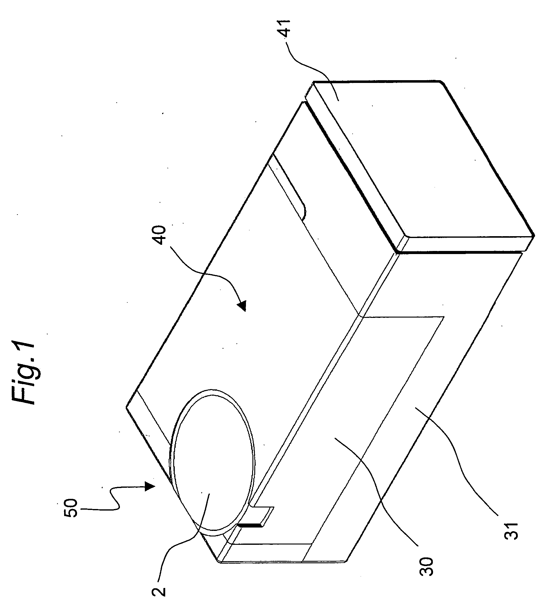
[0046]FIG. 1 shows a perspective view of a camera module in which a lens actuating device for actuating a zoom lens and a focusing lens in accordance with a first embodiment of the invention is installed.

[0047] As shown in FIG. 1, the camera module 50 has a gear case 30 having an imaging lens 2, an optical base 31 that is combined with the gear case 30 so as to constitute a housing for the lens actuating device 40, and an imaging device 41 fixed to the optical base 31. The gear case 30 and the optical base 31 are formed of resin having a rigidity.

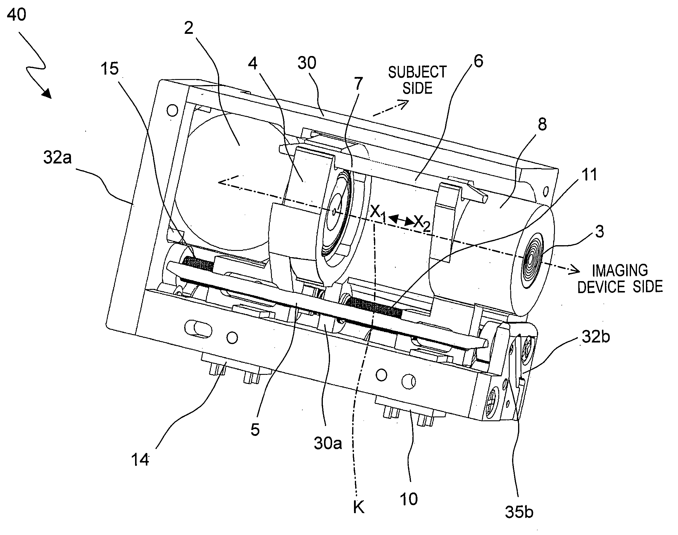
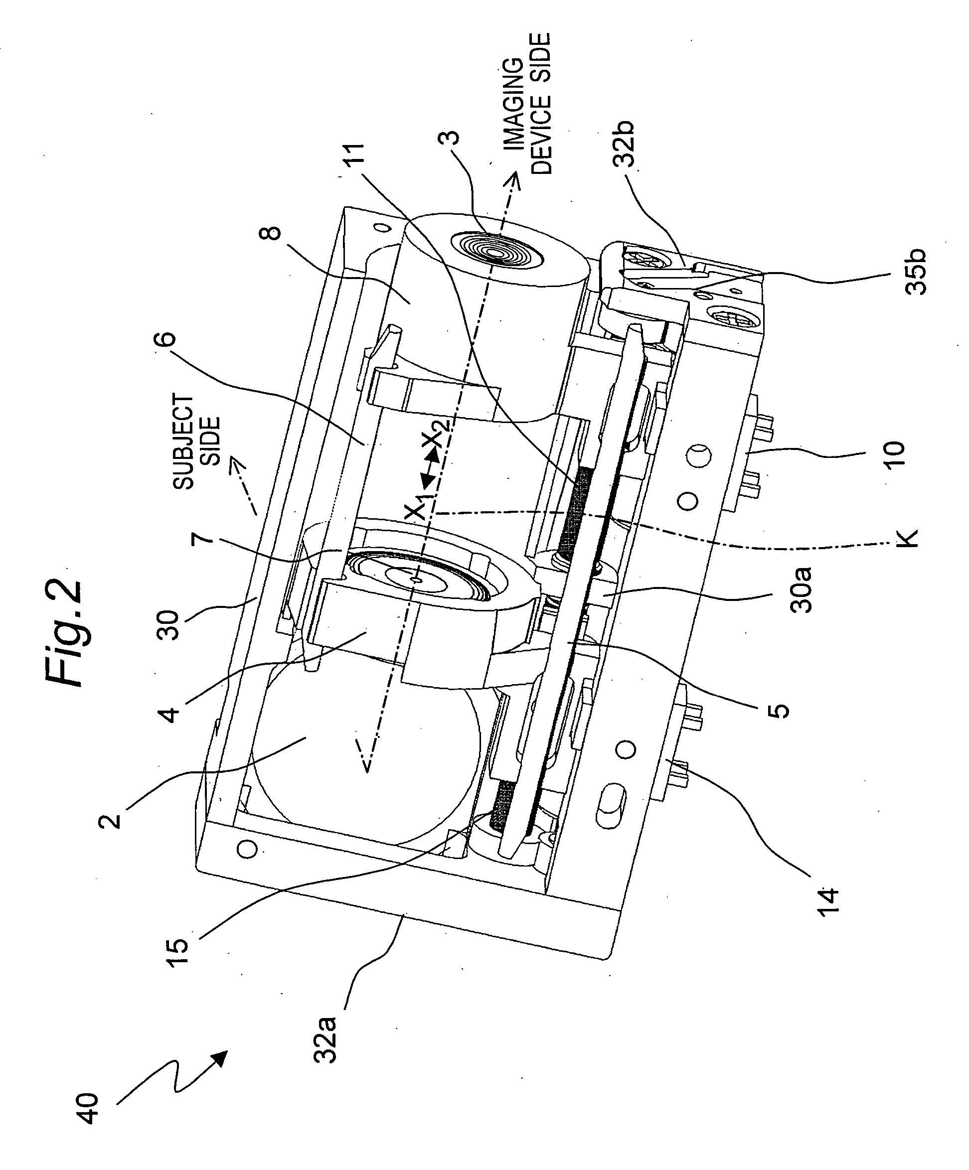
[0048]FIG. 2 shows a perspective view of a side of the gear case 30 in the lens actuating device 40 from which the optical base 31 (shown in FIG. 1) has been detached.

[0049] In an optical system of the camera module 50 in which the lens actuating device of the invention is installed, as shown in FIG. 2, incident rays of light that have passed through the imaging lens 2 fixed on the subject side are thereafter bent by 90 degrees by an opt...

second embodiment

[0074] A mobile phone as an example of portable electronic equipment in which a camera module is installed in accordance with of a second embodiment of the invention will be described with reference to FIGS. 7 through 10.

[0075] As shown in FIG. 7, the mobile phone 60 has a first casing 61 and a second casing 72 that are connected through a hinge 71. In the first casing 61, the camera module 50 (shown in FIG. 9) is installed in back of an imaging hole 65, and a sub-monitor 62 and sub-monitor operation buttons 63 are also installed. Speaker holes 64 are provided in the vicinity of the sub-monitor operation buttons 63, and a speaker 70 (shown in FIG. 9) is installed in back of the speaker holes 64. In the second casing 72 is installed a main circuit system (not shown) including operation buttons, a microphone, an antenna, a communication circuit, and memories. Thus, the second casing 72 has functions of communication, camera shooting, music player, and the like.

[0076]FIG. 8A shows a ...


PUM


Abstract

Power from a focusing motor (14) is transmitted via a gear (35a) to a focusing lead screw (15) so that a first lens holder (4) is moved in a direction of an optical axis. Power from a zooming motor (10) is transmitted via a gear (35b) to a zooming lead screw (11) so that a second lens holder (8) is moved in the direction of the optical axis. The first and second lens holders (4, 8), the focusing and zooming lead screws (15, 11), the focusing and zooming motors (14, 10), and the gears (35a, 35b) are contained in a housing (30, 31). The focusing motor (14) and the zooming motor (10) may be fixed to a gear case (30).

Description

[0001] This nonprovisional application claims priority under 35 U.S.C. §119(a) on Patent Application No. 2004-345652 filed in Japan on Nov. 30, 2004, the entire contents of which are hereby incorporated by reference. BACKGROUND ART [0002] The present invention relates to a lens actuating device, a camera module, and portable electronic equipment and particularly relates to a lens actuating device in which a zooming motor for actuating a zoom lens and a focusing motor for actuating a focusing lens are coaxially disposed, and a camera module and portable electronic equipment in which the lens actuating device is used. [0003] In an imaging apparatus such as video camera and video movie for taking pictures of a subject, generally, a zoom lens for adjusting a perspective of an image of the subject and a focusing lens for adjusting a focus of the image of the subject are provided, and the image of the subject that is to be captured is formed on an imaging device such as CCD. [0004] Among ...

Claims


Application Information

Patent Timeline
IPC IPC(8): G02B7/02
CPCG02B7/022G02B7/023G02B7/102
Inventor MIKI, RENZABURO
Owner SHARP KK
Why Eureka
Try Eureka