Method of detecting and correcting relay tack weld failures

Active Publication Date: 2006-06-01
ROBERTSHAW CONTROLS CO
View PDF10 Cites 26 Cited by
  • Summary
  • Abstract
  • Description
  • Claims
  • Application Information

AI Technical Summary

Benefits of technology

[0012] In a preferred embodiment of the present invention, the method attempts to recycle the relay. Preferably the number of recycles attempted is limited to prevent other damage from occurring in the relay control circuitry. For a magnetically held relay, the close coil is energized and de-energized a number of times in an attempt to break the tack weld. If the relay opens, the recycling of the relay is discontinued to preclude subsequent tack welding of the contacts. In an embodiment of the present

Problems solved by technology

Preferably the number of recycles attempted is limited to prev

Method used


Image

  • Method of detecting and correcting relay tack weld failures
  • Method of detecting and correcting relay tack weld failures
  • Method of detecting and correcting relay tack weld failures

Examples


Embodiment Construction

[0024] While the relay control method of the present invention may be implemented in any system that utilizes electromechanical relays, the following description will describe the operation of this method in the context of a method of controlling a compressor control relay in a consumer refrigerator. However, such an environment is utilized for illustrative purposes only, and is not limiting to the scope of the invention as defined by the appended claims. Additionally, while other environments in which the method finds applicability may be mentioned or discussed herein, such other implementations are also provided to give the reader context and aid in the understanding of the invention, and should also not be taken as limiting the scope of the invention.

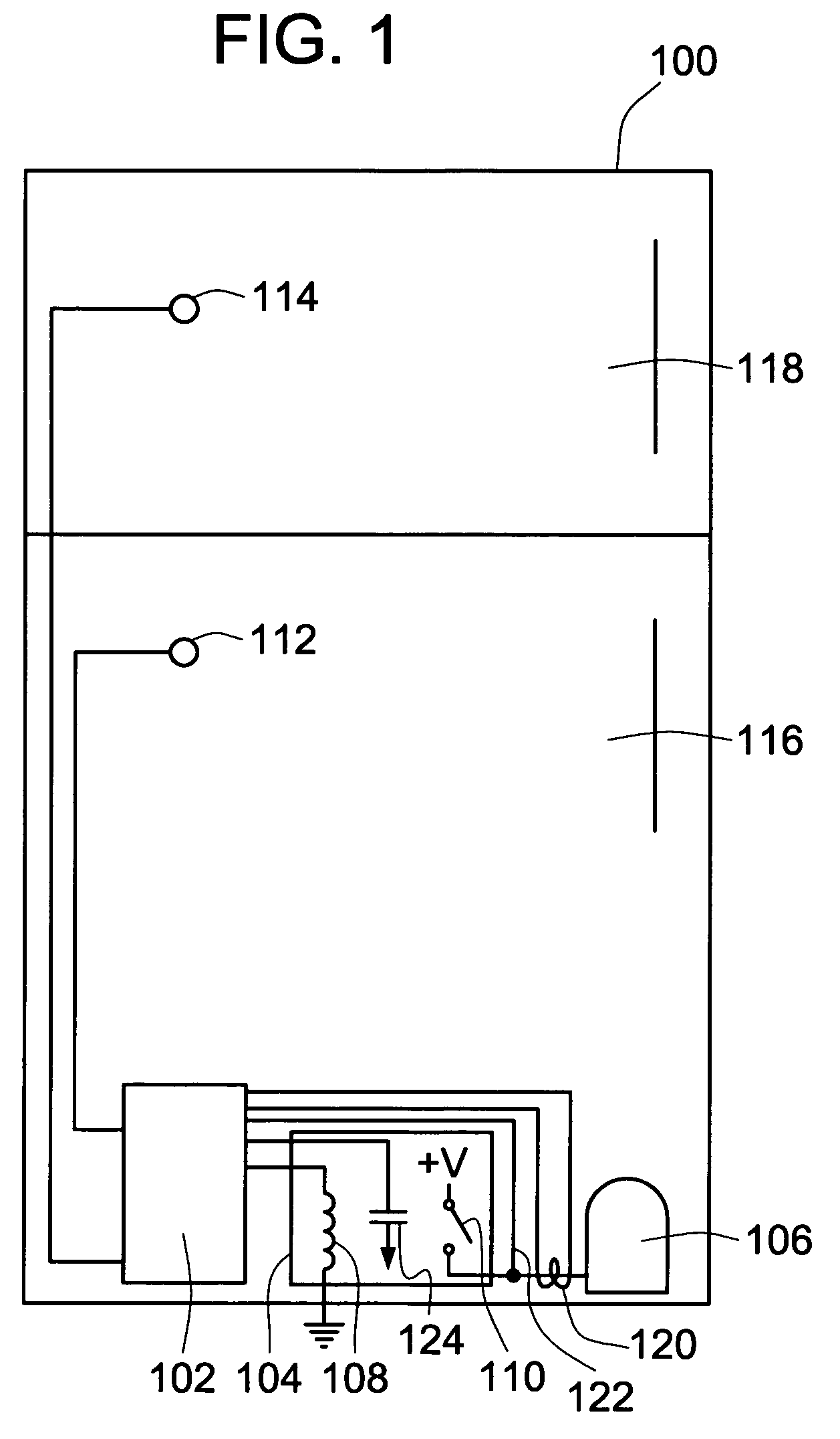
[0025] As illustrated in FIG. 1, a consumer or commercial refrigerator 100 typically includes some type of controller 102 that includes control logic, sensing circuitry, and, output control circuitry to control, for example, the com...


PUM


Abstract

A method of detecting and attempting to correct a relay tack weld failure of its contacts is presented. This method senses the failure of a relay's contacts to open once it has been commanded to trip. This sensing may directly sense relay conditions, or may indirectly determine the failure by sensing a system parameter that shows the effects of the failure. Once the failure of the relay to open has been determined, the relay is again energized in an attempt to break loose the relay tack weld. If the relay fails to open after this first attempt, the relay may again be repulsed. Preferably a relay check timer is utilized to ensure that the system has stabilized before a repulse is attempted. A relay pulse timer may be used to control the pulse duration during these attempts. The number of attempts may also be limited.

Description

FIELD OF THE INVENTION [0001] The present invention relates generally to relay control systems and methods, and more particularly to relay control systems and methods that address faulty relay operation. BACKGROUND OF THE INVENTION [0002] Relays have long been used in both consumer and commercial appliances and machinery to provide automated or electrically controlled switching operation. One of the benefits of such relays is that they allow the use of “low level” signals to switch “high level” power. That is, a typical relay includes at least one coil that pulls in or controls the switching of the main relay contacts. For some types of magnetically held relays, de-energization of the relay coil will cause the main relay contacts to open under action of a spring force or other mechanical bias. Such held relays, therefore, require that the coil be energized during the period of main contact closure (or opening in a normally-closed relay configuration). Another type of single coil rel...

Claims


Application Information

Patent Timeline
IPC IPC(8): H01H47/00
CPCH01H47/002H01H2047/003H01H45/00H01H47/22
Inventor LAURENT, TIM M.JOHNSON, MARK A.DEGENHART, THOMAS W.
Owner ROBERTSHAW CONTROLS CO
Why Eureka
Try Eureka