Illumination unit for aircraft

a technology for aircraft and abrasives, applied in the direction of mass transit vehicle lighting, landing aids, lighting support devices, etc., can solve the problems of not being able to install on just any desired surface, requiring a relatively deep installation depth, and a small fraction of light energy provided

Inactive Publication Date: 2006-06-01
AIRBUS OPERATIONS GMBH
View PDF19 Cites 11 Cited by
  • Summary
  • Abstract
  • Description
  • Claims
  • Application Information

AI Technical Summary

Benefits of technology

[0016] In one example, an extremely flexible, individually programmable, controllable illumination system is adaptable to changing requirements and situations.

Problems solved by technology

All these illumination devices are associated with the disadvantage in that they require a relatively deep installation depth.
Consequently, it is not possible to install them on just any desired surface because there is often not enough space behind such a surface for a corresponding installation.
Furthermore, due to the often covered installation a large part of light energy is reflected backwards or sideways, and hence only a small fraction of light energy provided is actually usable.

Method used


Image

  • Illumination unit for aircraft
  • Illumination unit for aircraft
  • Illumination unit for aircraft

Examples


Embodiment Construction

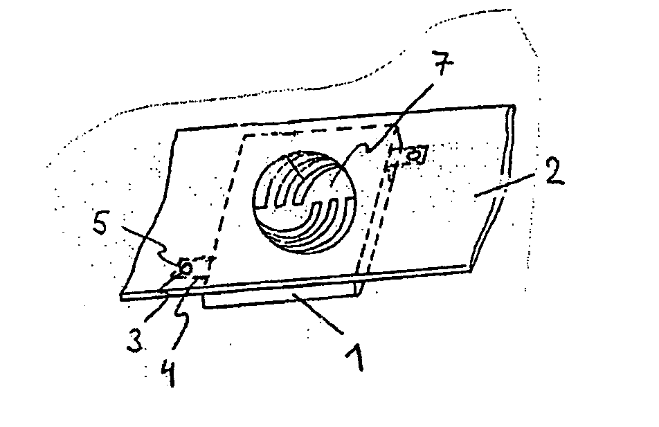
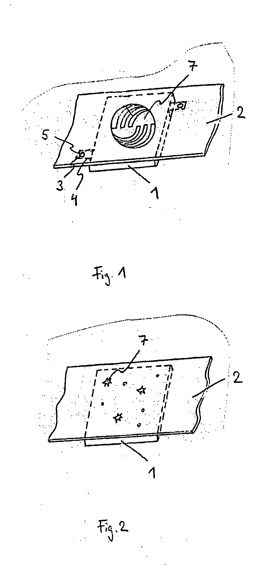
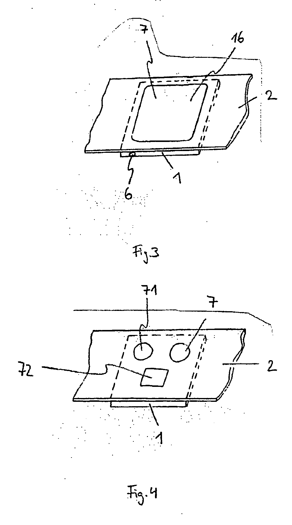
[0026]FIG. 1 shows a diagrammatic representation of an illumination unit according to one embodiment of the present invention. As shown in FIG. 1, the illumination unit comprises a two-dimensional light source 1, an aperture 2, which is at least partly translucent, and an attachment element 3. The two-dimensional light source 1 is firmly connected to the aperture 2 by way of the attachment element 3. An attachment region 4 which comprises a recess 5. As shown in FIG. 1, the attachment region 4 is an angle-shaped arrangement which is firmly connected to the two-dimensional light source 1. The attachment element 3, for example, is a screw, rivet or a self-locking plug-in bolt. It is also possible for the light source 1 to be clipped to the aperture 2 by means of a clip.

[0027] The aperture 2 is an interior fitting element of an aircraft cabin, wherein interior fitting element is a wall paneling, a ceiling element or a baggage locker. The two-dimensional light source 1 can be made in t...


PUM


Abstract

In present-day passenger aircraft, fluorescent lamps in tubular form, are used as general illumination. An illumination unit for aircraft having a two-dimensional light source, an aperture which is at least partly translucent, and an attachment element. In this arrangement, the aperture is an interior fitting element of an aircraft cabin so that the entire illumination unit can be integrated in the aircraft cabin when the interior fitting element is installed. The flat design of the light source makes the installation of the light source possible in spaces of limited depth.

Description

RELATED APPLICATIONS [0001] This application claims the benefit of the filing date of U.S. Provisional Patent Application No. 60 / 620,376 filed Oct. 20, 2004, the disclosure of which is hereby incorporated herein by reference, and claims the benefit of the filing date of German Patent Application 10 2004 051 146.2, filed Oct. 20, 2004.FIELD OF THE INVENTION [0002] The field relates to illumination systems for aircraft. In particular, the field relates to an illumination unit for an aircraft; and an aircraft comprising a corresponding illumination unit. TECHNOLOGICAL BACKGROUND [0003] In present-day passenger aircraft, fluorescent lamps in tubes are often used as general illumination. Furthermore, to display certain information in present-day passenger aircraft, so-called signs which display the information as text or as pictograms are used. For example, signs or illuminated panels for displaying instructions or warning notes such as for example “No smoking” or “Fasten seat belt,” are...

Claims


Application Information

Patent Timeline
Patent Type & Authority Applications(United States)
IPC IPC(8): F21V11/00
CPCB60Q3/025B60Q3/0253B60Q3/0256B60Q3/0283B64D11/00B64D2011/0038B64D2011/0053B64D2011/0061B60K2370/343B60Q3/43B60Q3/44B60Q3/46B60Q3/745
Inventor HEYM, DETLEFKOHLMEIER-BECKMANN, CARSTEN
Owner AIRBUS OPERATIONS GMBH
Why Eureka
Try Eureka