Pilot multiplexing method and OFDM transceiver apparatus in OFDM system

a transceiver and multiplexing technology, applied in multiplex communication, orthogonal multiplex, baseband system details, etc., can solve the problems performance and cost, and the influence of data demodulation performance, so as to remove inter-symbol interference and improve reception sensitivity.

Inactive Publication Date: 2006-06-01
FUJITSU LTD
View PDF30 Cites 48 Cited by
  • Summary
  • Abstract
  • Description
  • Claims
  • Application Information

AI Technical Summary

Benefits of technology

[0024] By virtue of the above-described embodiment of the present invention, momentary channel estimation can be carried out at receipt of one or two pilot symbols and sufficiently long spreading code can be used, thereby making it possible to multiplex a number of pilots.
[0025] Further, a transmitting apparatus according to the invention inserts a guard interval into an OFDM signal and a CDMA signal and removes inter-symbol interference.
[0026] Further, a receiving apparatus according to the present invention generates a replica signal of each pilot and subtracts replica signals of pilots other than a pilot of interest from a receive signal to thereby perform channel estimation of the pilot of interest. If this arrangement is adopted, reception sensitivity can be improved by utilizing an interference canceller.

Problems solved by technology

With the prior art, however, a problem is that the correlation characteristic is sluggish and, hence, it is difficult to improve detection precision.
A further problem is that this detection precision has an influence on data demodulation performance.
However, since CDMA transmission is performed only for the sake of synchronization, there are problems in terms of performance and cost.
However, with such prior art, each pilot cannot be demultiplexed until the code is received in its entirety.
Consequently, it is not possible to cope with an instance where a momentary channel estimation value is desired at the stage where one or two pilot symbols, for example, have been received.

Method used


Image

  • Pilot multiplexing method and OFDM transceiver apparatus in OFDM system
  • Pilot multiplexing method and OFDM transceiver apparatus in OFDM system
  • Pilot multiplexing method and OFDM transceiver apparatus in OFDM system

Examples


first embodiment

(A) First Embodiment

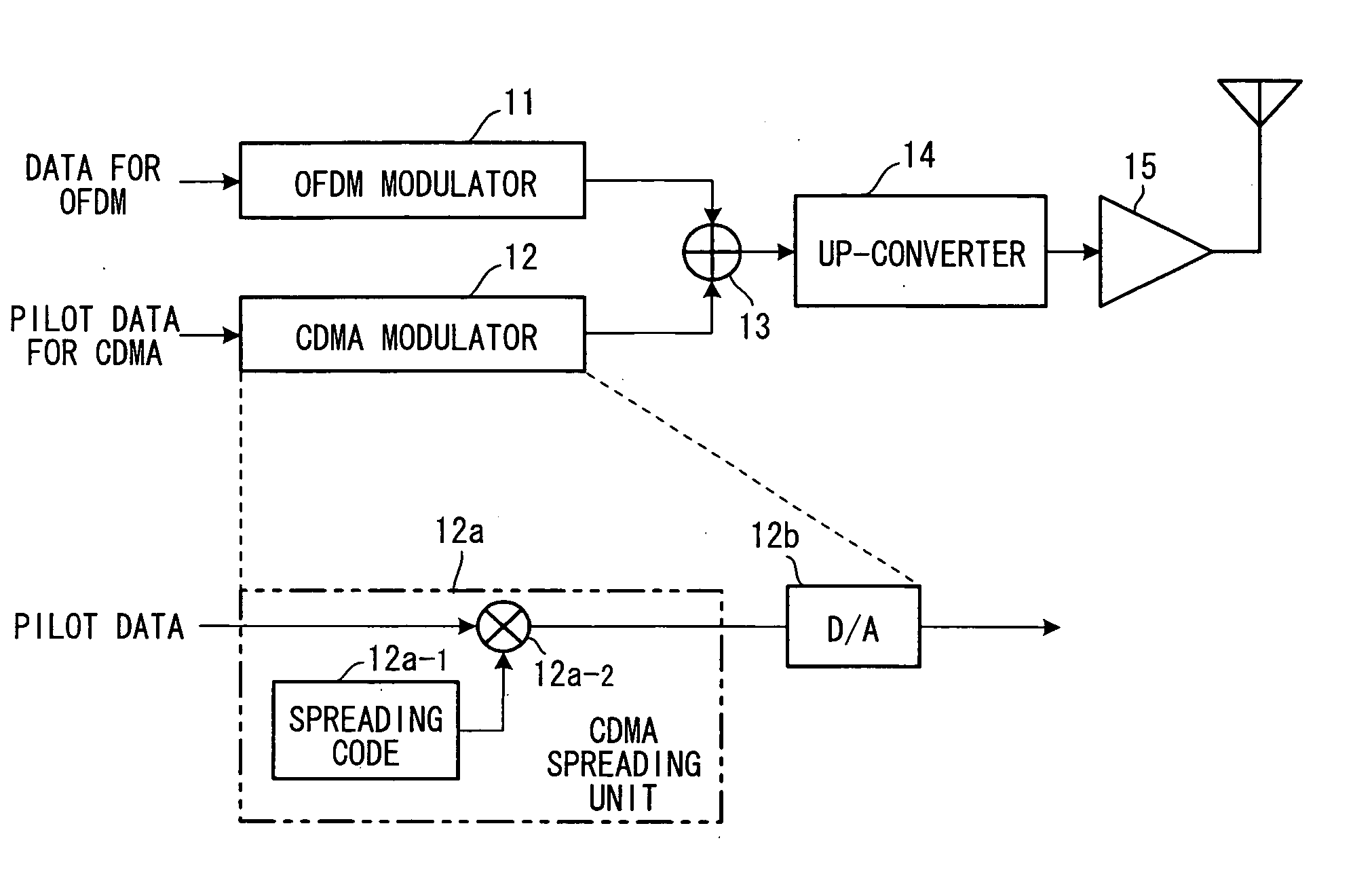
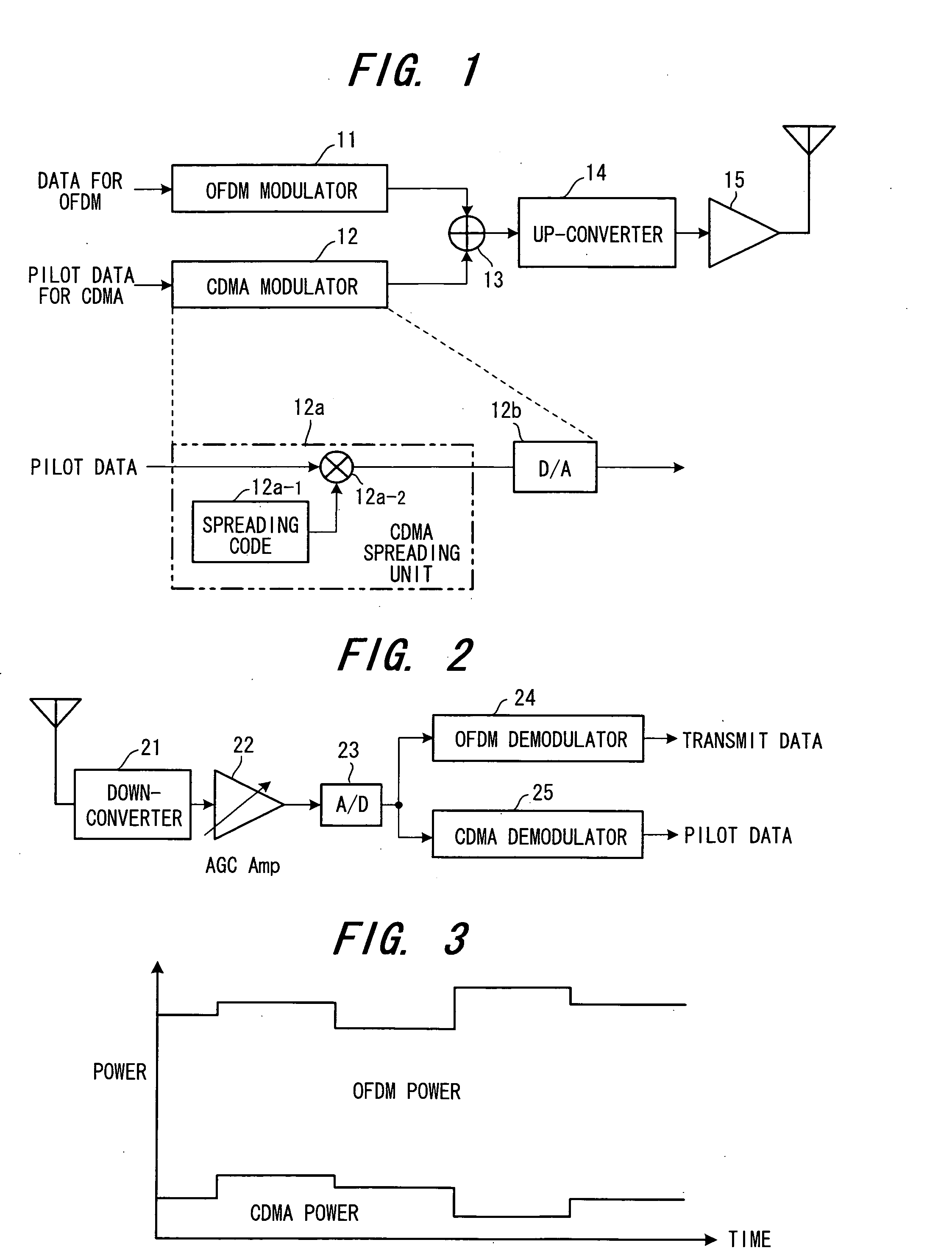
[0053]FIG. 1 is a diagram illustrating the structure of a transmitting apparatus in an OFDM system according to a first embodiment, FIG. 2 is a diagram illustrating the structure of a receiving apparatus in the OFDM system, and FIG. 3 illustrates an example of frame structure.

[0054] In the transmitting apparatus of FIG. 1, an OFDM modulator 11 has a structure identical with that of the OFDM modulator 1 in FIG. 17. The modulator applies OFDM modulation to transmit data, which enters at a prescribed bit rate, and outputs the result. A CDMA modulator 12, which has a CDMA spreading unit 12a and a DA converter 12b, spreads pilot data, which enters at a bit rate identical with that of the transmit data, by a spreading code for the pilot and outputs the result. In the CDMA spreading unit 12a, a spreading code generator 12a-1 generates the spreading code for the pilot, a multiplier 12a-2 multiplies pilot data by the spreading code to thereby directly spread the data, an...

second embodiment

(B) Second Embodiment

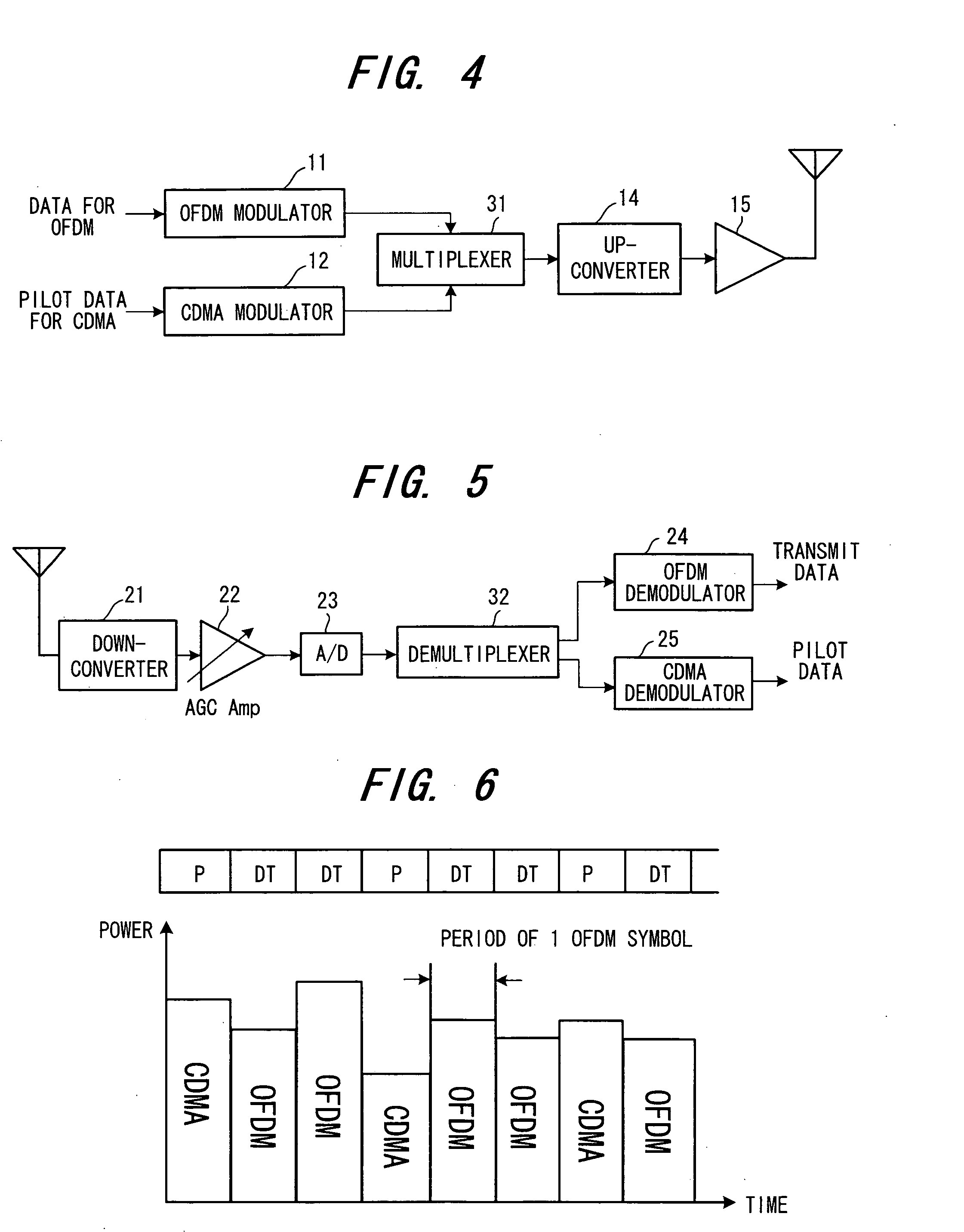
[0057]FIG. 4 is a diagram illustrating the structure of a transmitting apparatus in an OFDM system according to a second embodiment, FIG. 5 is a diagram illustrating the structure of a receiving apparatus in the OFDM system, and FIG. 6 illustrates an example of frame structure.

[0058] The transmitting apparatus of FIG. 4 differs from that of FIG. 1 in the following points:

[0059] ① the combiner 13 is changed to a multiplexer 31;

[0060] ② items of transmit data DT and pilot data P are input to the OFDM modulator 11 and CDMA modulator 12, respectively, at the timing shown in FIG. 6; and

[0061] ③ a multiplexer 31 selects and outputs CDMA signals and OFDM signals in time-division fashion at the timing shown in FIG. 6.

[0062] More specifically, in the transmitting apparatus of FIG. 4, the separately provided OFDM modulator 11 and CDMA modulator 12 input an OFDM signal and CDMA signal of the same frequency band, these signals being obtained by OFDM and CDMA modulation...

third embodiment

(C) Third Embodiment

[0068] In FIG. 7, (A) is a diagram showing the structure of a timing detection unit for detecting OFDM frame timing and OFDM symbol timing in a receiving apparatus.

[0069] The transmitting apparatus transmits the OFDM signal and CDMA signal by the arrangement of either the first or second embodiment, The CDMA signal is generated and transmitted by spreading known pilot data at a specific timing (e.g., the frame timing) by a known spreading code for timing.

[0070] A matched filter 41 in the timing detection unit of the receiving apparatus performs a correlation operation by multiplying the A / D-converted receive signal by the transmit-side known spreading code for timing. An averaging unit 42 calculates an average Xj of correlation at each time tj using a plurality of results of the correlation operation. A power calculation unit 43 calculates the power of the correlation value Xj at each time and generates a delay profile shown in FIG. 8. From the delay profile, a...


PUM


Abstract

Disclosed is a pilot multiplexing method in an Orthogonal Frequency Division Multiplexing (OFDM) system. Transmit data is transmitted by an OFDM signal through an OFDM scheme, pilot data is directly spread, and a spread-spectrum signal, which has been obtained by spreading, is transmitted in the same frequency band as that of the OFDM signal at the same time in superposition therewith or time-division multiplexed therewith. The spread-spectrum signal is a CDMA signal that has been obtained by spreading the pilot data by a prescribed spreading code.

Description

BACKGROUND OF THE INVENTION [0001] This invention relates to a pilot multiplexing method and transceiver apparatus in an Orthogonal Frequency Division Multiplexing (OFDM) system and, more particularly, to a pilot multiplexing method and OFDM transceive apparatus in an OFDM system for transmitting transmit data by an OFDM signal through an OFDM scheme, and transmitting pilot data by a spectrum signal, e.g., a CDMA signal, in a frequency band identical with that of the OFDM signal. [0002]FIG. 17 is a diagram of the structure of an OFDM transmitting apparatus in an OFDM (Orthogonal Frequency Division Multiplexing) transmission system. User data (channel data) is input to an OFDM modulator 1 serially at a prescribed bit rate. A serial / parallel converter la converts input data to M-bit parallel data S1 to SM, i.e., frequency-domain data of subcarriers f1 to fM, by a serial-to-parallel conversion. An IFFT unit 1b, which is for transmitting the frequency-domain data S1 to SM by the subcarr...

Claims


Application Information

Patent Timeline
Patent Type & Authority Applications(United States)
IPC IPC(8): H04J11/00H04L5/02H04L27/26
CPCH04B1/707H04B2201/70701H04L5/0016H04L5/0048H04L25/022H04L25/0226H04L27/261
Inventor HASEGAWA, TSUYOSHISHIMIZU, MASAHIKO
Owner FUJITSU LTD
Why Eureka
Try Eureka